Modbus is one of the most widely used communication protocols in industrial automation. Be it RTU or TCP IP, Modbus is widely implemented in many devices due to its simplicity, low cost, and reliability it offers. When working with Modbus, one must always be familiar with the way of data storage concept. Be it any protocol, it should be known how data is handled in them. Also, as Modbus has a good variety of data registers, engineers should know exactly how they function. In this post, we will see how data is stored in the standard Modbus protocol.
What is Modbus?
First of all, let us understand what Modbus is. Modbus is an industrial communication protocol developed by Modicon ( now Schneider Electric).
Modbus is based on the master-slave model, where the master sends requests for data, and the slave responds by giving data in return. It is a very simple concept of working. The number of slaves for a particular network is limited to 247. The hardware used for Modbus is RTU or TCP IP.
Standard Modbus Protocol
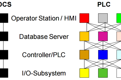
Refer to the image below for more understanding. As you can see, there are three variable frequency drives working as slaves, one PLC which acts as both master and slave, and the HMI which acts as a master. The slaves are connected in a bus topology (in RS485 hardware), all looped together and connected to a single PLC port, which will act as the master. The other port of the PLC is configured as a slave to send data to the HMI, which acts as a master, through RS-485 hardware.

When a master communicates with multiple slaves, it requests data from each slave one by one, and not simultaneously; otherwise, the network will not communicate. In response, when a particular slave is asked, it will send data to the master. If data is to be written in a slave device, then too the master will do this one by one, and not simultaneously. The RS-485 network will require bus topology, whereas TCP IP will work in star, tree, or ring topologies (as it is Ethernet).
Data Storage in Modbus
Let us first revisit our basics. One byte is 8 bits, and two such bytes make an integer or word. The word is unsigned (without any negative result), whereas an integer can be signed (with a negative result too) or unsigned. Two such integers make a floating point or double word (meaning a 32-bit data consisting of 4 bytes). Now, in Modbus, data is stored in a separate register. This register consists of four main types:
Coil (00000 – 09999)
Each coil stands for a single bit register. This means it can store either 0 or 1. Starting with 0, 0 is the logical address here for coil status. So, for example, the value of 00003 can be 0 or the value of 00042 can be 1. The coils status is read or write, meaning either you can read the bit value or write a bit value.
Discrete Input (10000 – 19999)
Each discrete input stands for a single bit register. This means it can store either 0 or 1. Starting with 1, 1 is the logical address here for the discrete input status. So, for example, the value of 10003 can be 0, or the value of 10042 can be 1. The coil’s status is read only, meaning you can only read the bit value and not write anything here.
Input Register (30000 – 39999)
Each input register stands for a single 16-bit register. This means it can store values from -32767 to 32767 if signed, or 0 to 65535 if unsigned. Starting with 3, 3 is the logical address here for the input register status. So, for example, the value of 30003 can be -45, or the value of 30042 can be 126. The input register is read-only, meaning you can only read the integer value and not write anything here.
Holding Register (40000 – 49999)
Each holding register stands for a single 16-bit register. This means it can store values from -32767 to 32767 if signed, or 0 to 65535 if unsigned. Starting with 4, 4 is the logical address here for holding register status. So, for example, the value of 40003 can be 324, or the value of 40042 can be 6791. The holding register is both read and write, meaning you can either read the integer value or write the integer value here.
Modbus Important Notes
Some important notes to consider in the data storage concept here are:
- When accessing Modbus registers, offsets are generally considered. The offset is usually 0, 1, or -1. For example, if you want to access 40065, depending on the PLC make, the register address in the PLC will come as 64, 65, or 66.
- Data can be floating too, so you can combine two registers to make a 32-bit data type for long integers or floating point data. In them, you have two parts to access – MSB (most significant bit) and LSB (least significant bit).
- For example, if you use two registers of 41056 and 41057 for reading 32-bit data, the MSB or the higher part will be 41056, and the LSB or the lower part will be 41057. Now, the main part comes here in the form of two ways of sending data – little Endian or big Endian. Modbus devices can send data as little Endian (value of LSB first and value of MSB then) or big Endian (value of MSB first and value of LSB then). So, for example, if slave is little Endian and master too is little Endian, then data will be read and written as it is. But if the master is a big Endian, then data swapping logic will be required in the master, where MSB first and LSB later will be interchanged with LSB first and MSB later. So, whenever you access Modbus values, always take care of the way the slave communicates data.
In this way, we saw how data is stored in the standard Modbus protocol.
Read Next:
- Introduction to Modbus Reading and Writing
- How Modbus Communication Works
- Why is Baud Rate Important in Modbus Network?
- Modbus Communication Interview Questions
- ModScan Software for Modbus Communication