Safety Instrumented System (SIS) – Verification & Validation are very critical for the safe implementation & functioning of SIS.
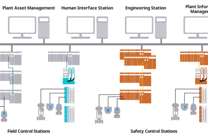
Safety Instrumented System
The performance of any new Safety Instrumented Systems is to be verified and validated before the system is taken into service. Certain steps in the SIS Work Process comply with the requirements of SIS Verification & Validation.
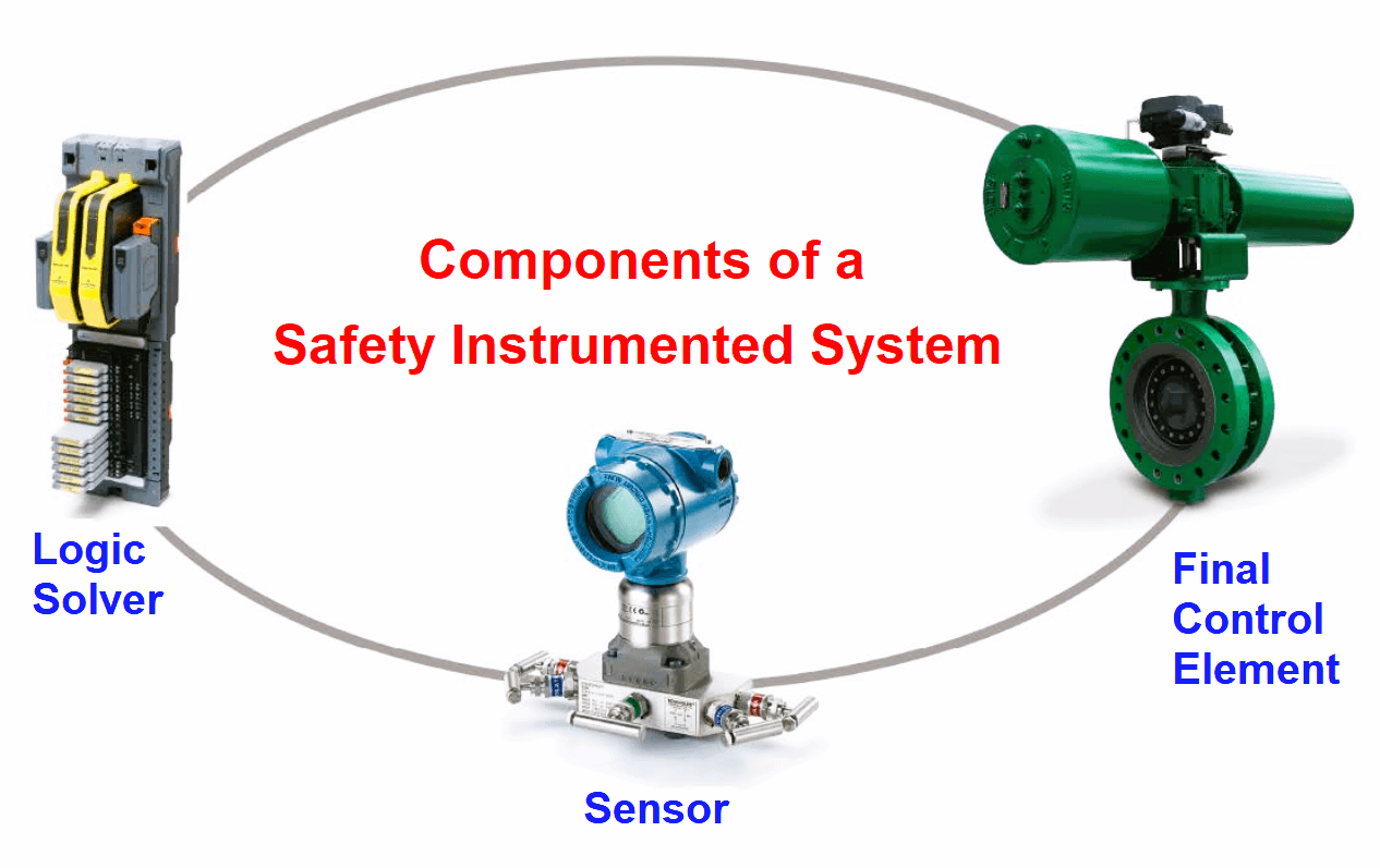
It is necessary to use written loop verification procedures for the loop check and commissioning of the SIF sensors, logic solver, and final elements.
Validation procedures shall functionally test the entire system during initial validation Each element in a SIL loop from the measuring element through the logic solver to the final control device shall be validated as defined in the validation procedure to fulfill the Safety Instrumented Function (SIF).
Detailed approach:
SIS Verification
SIS Verification is the activity of confirming by examination checking of the SIS instrument – Sensor, Logic solver & Final control element meets the SIS design requirements of the safety function have been fulfilled.
Various Steps in SIS Verification
- Verification according to the SIS Work Process covers loop design, instrument selection, instrument installation, logic solver hardware, and software for Instrumented Protection Layers under BPCS and SIS.
- Written verification procedures, measures, and techniques including implementation
- Roles involved with SIS Verification including personnel names, departments, and organizations responsible for these activities.
- Software program to be verified for proper coding, system memory, redundancy required and then subjected to coach review.
- Verification is conducted in two phases:
- Design verification involves the detailed check of instrument and automation design documentation prior to the approval of the final design.
- Installation verification intends to verify the field installation and final software application code as per the functional requirements and implementation of applicable safety standards
- Various supporting tools required
- Completeness of the SIS implementation and the traceability of the requirements
- SIS documents auditability of the documentation confirming completion of SIS Verification performed.
SIS Validation
SIS Validation is the activity of demonstrating by inspection and testing that the safety-related system under consideration, after installation, meets in all respects the safety requirements specification (SRS) for that safety-related system.
The performance of Safety Instrumented Systems shall be both verified and validated before being placed into service.
Validation is the one-time process in the entire SIS Lifecycle which is performed before the commissioning of a particular system/loop.
Steps in SIS Validation
SIS Validation procedure shall be developed by a team of the Instrument Design Lead, and an Operations representative.
Define all activities required to test the SIS loop including timing for specific tasks with responsible personnel and the expected results.
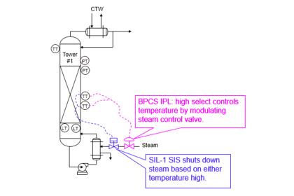
Validation involves bringing all available sensors (for the SIS Loop under commissioning) to the alarm condition, verifying activation of the appropriate alarm, and ensuring the moving of the final elements to their failsafe position within the specified time.
Confirming the logic solver activate the required outputs and operator interfaces, and the field verifies the movement of the final elements to their failsafe position within the specified time. This full-loop validation applies to new or modified SIS and for BPCS with LOPA scenario.
Validation Procedure of Application Program
Validation of the application program shall determine whether:
All of the specified application program safety requirements are correctly performed;
The application program does not jeopardize the safety requirements under SIS fault conditions and in degraded modes of operation and for BPCS fault conditions for any interfaces between the SIS and BPCS
The application program does not jeopardize the safety requirements by executing ’unused’ software functionality.
Restoration after SIS Validation
- After the SIS validation and prior to the identified hazards being present, the following activities shall be carried out:
- All bypass functions (e.g., logic solver and sensor forces, disabled alarms) shall be returned to their normal position
- All process isolation valves shall be set according to the process start-up requirements and procedures
- All test materials (e.g., fluids) shall be removed
- All commissioning overrides and force permissive shall be removed.
Quite often the SIS bypasses are forgotten to be restored to normalcy due to the urgency of equipment/system/plant startup. This is very vital and proper care shall be taken to restore the bypasses and timer/constant settings to the actual running conditions.
Reference:
IEC 61511: “Functional safety – Safety instrumented systems for the process industry sector”
If you liked this article, then please subscribe to our YouTube Channel for Electrical, Electronics, Instrumentation, PLC, and SCADA video tutorials.
You can also follow us on Facebook and Twitter to receive daily updates.
Read Next: