Safety Integrity Level (SIL) is a measure of safety system performance – not a measure of process risk. The higher the level of risk, the greater the system performance required.
Based on a hazard and risk analysis, each individual Safety Instrumented Function (SIF) is assigned a required performance level, or SIL. Safety Instrumented Systems may have different SILs for each of its individual SIFs.
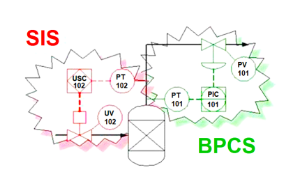
Difference between SIS, PLC and BPCS

HOW TO CALCULATE INTEGRITY LEVEL
Industrial plants require a multidiscipline team to evaluate and assign SIL performance levels for SIFs, not a specific person.
Common departments assigned to the team are process, mechanical design, safety, operations and control systems. Quantitative or qualitative analysis is used to calculate the SIL of each SIF:
1. ALARP, Risk Matrix and Risk Graphs
ALARP (As Low As Reasonably Practicable), Risk Matrixes and Risk Graphs are qualitative methods of determining SIL.
Qualitative data is faster and easier, but is also subjective and many engineers are not comfortable using this data to assign performance levels. Systems analyzed using qualitative data are often built too conservatively, adding unnecessary costs.
2.LOPA (Layer of Protection Analysis)
LOPA is a quantitative method that identifies and analyzes the effects of independent layers of protection (IPL) – devices, systems or actions capable of preventing a hazardous event.
LOPA are extremely detailed and require members of an organization to agree on risk tolerance levels. Quantitative analysis typically delivers lower levels of required performance, reducing safety system costs.

Once SILs are assigned using quantitative or qualitative analysis and independent protection layers considered, a Safety Requirement Specifications (SRS) is written to describe the functional and integrity requirements of the system.
Functional requirements describe the system inputs, outputs and logic. Integrity requirements describe the performance needed for each function.
Incomplete or incorrect specifications cause 44% of accidents in safety applications, stressing the importance of fully understanding the functional and integrity requirements of the system.

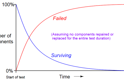
Device failure rates – dangerous detected (DD), dangerous undetected (DU), safe detected (SD) and safe undetected (SU) – are required to calculate SIL.
Failures In Time (FITs) is the data owner/operators require to calculate of Probability of Failure on Demand (PFD), Safe Failure Fraction (SFF), Risk Reduction Factor (RRF), Safety Availability (SA) and Mean Time to Failure (MTTF). This FIT data makes calculating target SIL levels rather easy for simplex systems.

To really understand a SIL rating you need to know what the Probability of Failure on Demand (PFD) is. The PFD is a likelihood that a loop will fail when a demand is placed on it. The PFD of a SIF is calculated using the number of potential dangerous undetected failures and the test interval of the loop.
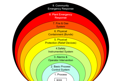
Safety instrumented systems are used to implement SIFs as layers of protection to reduce process hazards. Its an automated way to take an action against a potentially unsafe condition and return a process to a safe or stable state.
Some major differences between a SIS, PLC and BPCS hardware are :
- a Standard BPCS has unknown failure modes
- a SIS PLC will fail safely within a specified probability (SIL)
- a SIS PLC is certified to standards like IEC61508 for use in a safety application
- Safety PLC must be configured by person with appropriate competency in both safety and the development platform.
Also Read: Safety Instrumented Systems Interview Questions
A single SIS PLC can have any number of safety instrumented functions being controlled within it depending on how many unsafe conditions can exist in a facility, or area of a facility.
Most safety loops are designed to be configured as a de-energize to trip system, where the SIS PLC must remove power to trip the loop.
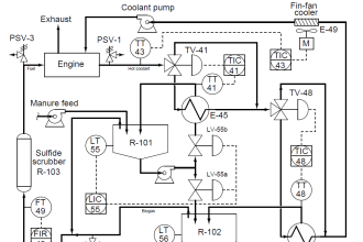
Sensing elements that are typically connected to a SIS are Pressure Transmitters, Level Transmitters, Temperature Transmitters, Flame Detectors, Smoke Detectors, Toxic Gas Detectors, Emergency Shut Down (ESD) switches, and any number of input devices.
Final elements are typically Solenoid Operated Valves (SOV), Beacons, Horns, Exhaust Fans, and Doors to name a few.
One thing to always keep in mind is that a SIS is not just a controller for a system. A SIS includes all transmitters and final elements, as well as associated solenoids, exhaust valves, and loop splitters. Any component where its failure could cause a potential failure on the loop is a component that is included in the SIS.
Dangerous failures occur when a component is unavailable when a demand is required. Device diagnostics greatly reduces the chance of dangerous failures. Safe failures, also known as nuisance /spurious trips, often lead to unplanned shutdowns. Sensor voting logic is commonly used to avoid nuisance trips and improve system performance.
IMPORTANCE OF INDEPENDENT SYSTEMS
Safety Instrumented Systems are required in the process industry because BPCSs are not perfect. Many industrial standards and guidelines recommend that the SISs be separate from the BPCS.
“A device used to perform part of a safety instrumented function shall not be used for basic process control purposes, where a failure of that device results in a failure of the basic process control function which causes a demand on the safety instrumented function, unless an analysis has been carried out to confirm that the overall risk is acceptable.” – ANSI/ISA 84.00.01-2004 11.2.10.
Human issues are the most common reason why SISs and BPCSs are independent. People cannot be trusted to make safe decisions during emergencies, no matter how well trained.
A study analyzing human performance in life threatening situations discovered that people make the wrong choice 99% of the time when required to do so in less than one minute, emphasizing the importance of an automated SIS to protect against hazardous events.
If components are allowed to be shared between SIS and BPCS, specifications may be overlooked leading to serious consequences. Separating the SIS from the BPCS assures that Safety Requirement Specifications (SRS) are reviewed before changes are made, and all new potential hazards caused by the proposed change will be identified before the change can be implemented.
Consideration should be given to using devices that are differentiated by color, unique tags or a numbering system to help differentiate from BPCS devices.
SIS vs. BPCS
Safety instrumented Systems are passive and dormant, monitoring and maintaining the safety of the process. These systems operate for long periods of time in which they simply wait to respond to a system demand.
Diagnostics are critical in SISs to ensure that components are functioning properly, reducing the frequency of manual tests. Changes after installation are subject to strict adherence to management of change (MOC). Even the smallest change can have a significant consequence.

Basic Process Control Systems (BPCS) are active and dynamic, controlling the process. These systems have a variety of digital and analog inputs and outputs that react to logic functions, making most failures self-revealing. Changes to BPCSs are very common and required to maintain accurate process control.
COMMON CAUSE FAILURES
Separating the SIS from the BPCS greatly reduces the risk of common cause failures, systematic failures that affect the entire system. Common cause failures can include loss of power, bugs in software or undetected device failures.
Assumptions are made that installing redundant components will lead to a safer and more reliable system, but more is not always best. Typically, more components lead to more complexity in the system, leading to more problems.
Common cause failures are often triggered by temperature fluctuations, equipment vibration, radio frequency interference or power surges. The greater the performance level required of a SIF, the more aware you must be to common cause failures.
The ideal way to prevent common cause failures is to install redundant devices with diverse technologies and physically separate the devices. For example, if you install a safety differential pressure transmitter to monitor a level application, you should also consider installing a gauge pressure mechanical switch in the event you lose power to the transmitter.
Recommended methods to reduce these failures are:
- use of redundant devices
- install devices with diagnostics
- choose diverse technologies
- physically separate devices
WHICH TECHNOLOGY TO CHOOSE
CERTIFIED vs. PROVEN-IN-USE
A common question asked by many owner/operators is whether they should use certified or proven-in-use devices in their SISs. ANSI/ISA 84.00.01-2004 in no way mandates the use of certified components in a SIS.
Some manufactures provide “proven-in-use” or “SIL suitable” components that are not certified to IEC 61508. Manufacturers that supply proven-in-use components are required to provide quality programs, demonstrate acceptable performance levels in similar environments and prove a volume of experience..
The primary advantage of using certified devices is the ease of access to failure rate data (FITs) collected by an independent third party. If considering a “proven-in-use” or “SIL suitable” device, vendor’s field return data is often used to provide failure rate data, but this data does not accurately represent total device failures and is not independently analyzed.
Data collected by a certified, independent third party allows owner/operators the ability to quickly calculate required performance level (SIL) of their SIFs with reliable and tested data.
Owner/operators can elect to install non-certified components, referred to as “proven-in-use” or “SIL suitable” in their SISs. This information is often available in facility maintenance records, vendor field return data and third-party databases. Non-certified component failure rate data is often inaccurate.
Manufacturers use field return data to calculate product failure rates, but this data is dependent on customer returns. Further, facility maintenance records are not always up to date with device failure information unless an automated Maintenance Software Management System is installed. Use caution when considering devices that do not have independent third-party failure rate data.
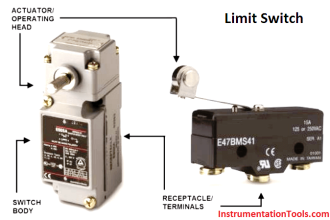
TRANSMITTER vs. SWITCH
You should consider installing both transmitters and switches in SISs. Transmitters are usually the first component considered in SISs due to the increased diagnostics, field indication, lower failure rates, and improved accuracy and repeatability.
But thought should be given to include redundant and diverse technologies to avoid common cause failures in a system. Transmitters require power to operator and only provide control through a PLC or DCS.
What happens if you lose power? What happens if the PLC or DCS fail? What happens if the transmitter electronics fails? In this case, a mechanical switch will continue to operate and protect in the event a hazardous situation develops. By installing redundant devices, risk is reduced by avoiding common cause failures.
NUISANCE TRIPS
Nuisance trips are referred to as safe failures in SISs. Mean time to failure (MTTFspurious) is the term used in SIS calculations to determine when a device will suffer a safe failure.
Safe failures occur when a device fails in a way in which the owner/operator is aware of the failure, typically an alarm or warning via the PLC or DCS. Safe failures are a nuisance to owner/operators and have economic consequences of lost production and downtime.
After a shutdown, it is required that manual action be taken by the owner/operator to reset the system – it is not allowed to be restarted automatically.
The best way to avoid these nuisance trips is through sensor channel voting in a PLC or DCS. Voting logic compares device channels and determines the action required.

It is important to understand the difference between safe and fault-tolerant. 1oo1 is very safe but is not fault-tolerant, meaning any measurement outside a sensor’s programmed range will cause a shutdown.
2oo2 is very fault-tolerant but is not as safe as 1oo1 because it requires two channels to agree before a shutdown occurs. 2oo3 is a suitable trade-off of both dual modes. 1oo2D is the preferred configuration to reduce nuisance trips and improve safety.
COMMUNICATION & DIAGNOSTICS
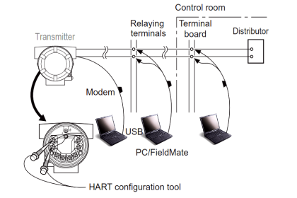
Component signals are commonly sent and received through a PLC or DCS. ANSI/ISA 84.00.01-2004 recommends that field devices be write-protected in the PLC or DCS to avoid the risk of making changes to a device outside the Safety Requirement Specification.
Bi-lateral communication, such as HART or Foundation Fieldbus, is important in BPCS devices but is not useful in SIS. In fact, increasing cyber security threats highlights the importance of requiring devices be write-protected in the event device safety variables are manipulated during an attack. When installing SIS sensors, bi-lateral communication is not necessary and only adds additional and unnecessary cost.
Device diagnostics continue to improve and provide owner/operators the health status of devices in their SISs. This information reduces the dangerous failure rates of the device by identifying when and how a device fails. Owner/operators can then quickly replace the faulty device to ensure their process is being properly protected.


thank you for the article
Great and thanks.
The key differences between Control System (DCS/BPCS) and the Safety system (SIS/ESD) are below.
Control Systems
* Control system works 24 / 7 (hours per day/days per week)
* No guarantee on the state of outputs during failure of control system, most likely outputs on hold
* High flexibility needed to develop and maintain (complex) control and automation applications
* Improvements or changes in the configuration but also repairs are mainly implemented on-line
* Accepted risk of plant disturbance in order to avoid a maintenance shut-down of the plant
* No need to test control system regularly except for some back-up/redundant parts
Safety Instrumented Systems
* Safety system always works on hot standby “Sleeping” mode. (On-demand mode)
* Predictable state of output on any revealed failure in the system “Failsafe” design
* Fixed functionality, carefully minimized during design
* No modification of safeguarding functionality in a running plant
* Stringent procedures to make any change
* Limited possibilities to repair the hardware while the plant is running
* Explicit procedure and strategy to test for unrevealed failures of instrumented protective functions
* Automatic tests (that are intended to reduce risk of unrevealed failures): line monitoring, partial stroke testing