Let’s study the working converters in Siemens PLC programming commands: BCD to Integer, Integer to BCD, Integer to Double Integer, BCD to Double Integer, Double Integer to Real.
Siemens PLC programming
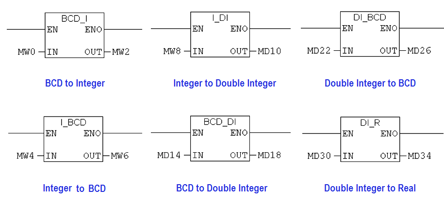
Data types are used to identify the type of data used in the user program. Its a data storage format that can contain a specific type or range of values. When PLC program stores data in variables must be assigned to specific data type like Bool (1 Bit), integer (16 bit), Word (16 bit), Double Integer (32 bit) and Real (32 bit).
While processing inputs and outputs in PLC program, conversion like BCD to an integer, Integer to a double integer, etc are much needed.
BCD to Integer Instruction
BCD to Integer instruction is used to convert BCD coded number to integer format. Input data can be read at IN. Input condition can give EN input and ENO is output, it has the same signal as EN. The least significant bit in BCD format is the sign bit.
Example 1:
Input IN : 0000 0001 0001 1000
Output OUT : 118
Example 2:
Input IN :1000 0001 0001 1000
Output OUT : -118
Integer to BCD Instruction
Integer to BCD instruction is used to convert integer format to BCD coded numbers. Input data can be read at IN. Input condition can give EN input and ENO is output, it has the same signal as EN.
Example 1:
Input (IN) : 118
Output (OUT) : 0000 0001 0001 1000
Example 2:
Input (IN): -118
Output (OUT): 1000 0001 0001 1000
Integer to Double Integer Instruction
Integer to Double Integer instruction is used to convert the data which is in 16 bit to 32 bit. Input data can be read at IN. Input condition can give EN input and ENO is output, it has the same signal as EN.
Example 1:
Input (IN) : 90
Output (OUT) : L # 90 (Decimal Format )
Example 2:
Input (IN): 0000 0000 0101 1010
Output (OUT): 0000 0000 0000 0000 0000 0000 0101 1010 (Binary format)
BCD to Double Integer Instruction
BCD to Double Integer instruction is used to convert BCD coded numbers to double integer format(32 bit ). Input data can be read at IN. Input condition can give EN input and ENO is output, it has the same signal as EN. The least significant bit in BCD format is the sign bit.
Example 1:
Input IN : 0000 0010 0101 0101
Output OUT : 255
Example 2:
Input IN :1000 0100 0100 0010 1000 0010 0101 0101
Output OUT : -4428255
Double Integer to BCD Instruction
Double Integer to BCD instruction is used to convert a double integer format(32 bit ) to BCD coded number. Input data can be read at IN. Input condition can give EN input and ENO is output, it has the same signal as EN. The least significant bit in BCD format is the sign bit.
Example 1:
Input IN : 225
Output OUT : 0000 0010 0101 0101
Example 2:
Input IN : -4428255
Output OUT : 1000 0100 0100 0010 1000 0010 0101 0101
Double Integer to Real Instruction
Double Integer to Real instruction is used to convert a double integer format(32 bit ) to a floating-point number (32bit). Input data can be read at IN. Input condition can give EN input and ENO is output, it has the same signal as EN. The least significant bit in BCD format is the sign bit.
Example 1:
Input IN : 987
Output OUT: 987.0
Example 2:
Input IN: 209834
Output OUT: 209834.0
Ladder Logic
Ladder Description
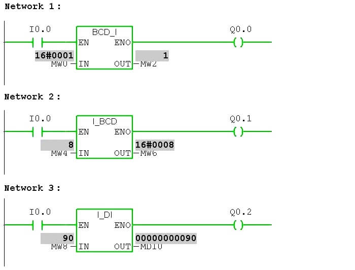
Network 1:
Input I0.0 is pressed, BCD to I instruction reads the value in MW0 and convert that to a corresponding integer value and result in the output to MW2. Q0.0 enables as long as I0.0 enables.
Network 2:
Input I0.0 is pressed; I to BCD instruction read the value in MW4 and convert that to corresponding BCD value and result in the output to MW6. Q0.1 enables as long as I0.0 enables.
Network 3:
Input I0.0 has pressed I to DI instruction reads the value in MW8 and convert that to a corresponding integer value and result in the output to MD10. Q0.2 enables as long as I0.0 enables.
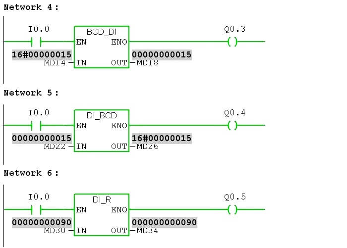
Network 4:
Input I0.0 is pressed; BCD to DI instruction reads the value in MD14 and convert that to corresponding double integer value and result in the output to MD18. Q0.3 enables as long as I0.0 enables.
Network 5 :
Input I0.0 is pressed, DI to BCD instruction reads the value in MD22 and convert that to corresponding BCD value and result in the output to MD26. Q0.4 enables as long as I0.0 enables.
Network 6:
Input I0.0 is pressed; DI to R instruction reads the value in MD30 and convert that to corresponding floating-point value and result in the output to MD34. Q0.5 enables as long as I0.0 enables.
Variable Table:

Variable is used to view the inputs and outputs in different formats.
In Siemens, MW is the address used for integer data, MD is the address used for double integer data.
Status Value in Variable table is used to see the input and output values.
Modify the value in the variable table is used to give input data.
Author: Hema Sundaresan
If you liked this article, then please subscribe to our YouTube Channel for PLC and SCADA video tutorials.
You can also follow us on Facebook and Twitter to receive daily updates.
Read Next:
- Bitwise Logical Operations
- PLC Packaging System
- Memory Instructions in PLC
- PLC Profinet I/O System
- Pulse Timer Instruction in PLC
