Inst ToolsInst ToolsInst Tools
  • Courses
  • Automation
    • PLC
    • Control System
    • Safety System
    • Communication
    • Fire & Gas System
  • Instrumentation
    • Design
    • Pressure
    • Temperature
    • Flow
    • Level
    • Vibration
    • Analyzer
    • Control Valve
    • Switch
    • Calibration
    • Erection & Commissioning
  • Interview
    • Instrumentation
    • Electrical
    • Electronics
    • Practical
  • Q&A
    • Instrumentation
    • Control System
    • Electrical
    • Electronics
    • Analog Electronics
    • Digital Electronics
    • Power Electronics
    • Microprocessor
  • Request
Search
  • Books
  • Software
  • Projects
  • Process
  • Tools
  • Basics
  • Formula
  • Power Plant
  • Root Cause Analysis
  • Electrical Basics
  • Animation
  • Standards
  • 4-20 mA Course
  • Siemens PLC Course
Reading: Shunt-Wound Motor Operation
Share
Font ResizerAa
Inst ToolsInst Tools
Font ResizerAa
  • Courses
  • Design
  • PLC
  • Interview
  • Control System
Search
  • Courses
  • Automation
    • PLC
    • Control System
    • Safety System
    • Communication
    • Fire & Gas System
  • Instrumentation
    • Design
    • Pressure
    • Temperature
    • Flow
    • Level
    • Vibration
    • Analyzer
    • Control Valve
    • Switch
    • Calibration
    • Erection & Commissioning
  • Interview
    • Instrumentation
    • Electrical
    • Electronics
    • Practical
  • Q&A
    • Instrumentation
    • Control System
    • Electrical
    • Electronics
    • Analog Electronics
    • Digital Electronics
    • Power Electronics
    • Microprocessor
  • Request
Follow US
All rights reserved. Reproduction in whole or in part without written permission is prohibited.
Inst Tools > Blog > Electrical Theory > Shunt-Wound Motor Operation

Shunt-Wound Motor Operation

Last updated: July 29, 2018 12:26 pm
Editorial Staff
Electrical Theory
No Comments
Share
2 Min Read
SHARE

The speed-torque relationship for a typical shunt-wound motor is shown in Figure 8.

A shunt-wound DC motor has a decreasing torque when speed increases. The decreasing torque-vs-speed is caused by the armature resistance voltage drop and armature reaction. At a value of speed near 2.5 times the rated speed, armature reaction becomes excessive, causing a rapid decrease in field flux, and a rapid decline in torque until a stall condition is reached.

Shunt-Wound DC Motor

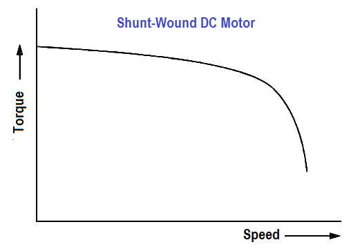
Figure 8 : Torque-vs-Speed for a Shunt-Wound DC Motor

Shunt-Wound Motor Applications

The characteristics of a shunt-wound motor give it very good speed regulation, and it is classified as a constant speed motor, even though the speed does slightly decrease as load is increased.

Shunt-wound motors are used in industrial and automotive applications where precise control of speed and torque are required.

Compounded Motor

The compounded motor is desirable for a variety of applications because it combines the characteristics of a series-wound motor and a shunt-wound motor. The compounded motor has a greater torque than a shunt motor due to the series field; however, it has a fairly constant speed due to the shunt field winding. Loads such as presses, shears, and reciprocating machines are often driven by compounded motors.

Don't Miss Our Updates
Be the first to get exclusive content straight to your email.
We promise not to spam you. You can unsubscribe at any time.
Invalid email address
You've successfully subscribed !

Continue Reading

Calculate Power in Parallel RC Circuit
Block Diagram
Power Factor Meter Principle
Parallel Short Circuit Faults
Power Factor
AC Induction Motor Slip
Share This Article
Facebook Whatsapp Whatsapp LinkedIn Copy Link
Share
Leave a Comment

Leave a Reply Cancel reply

Your email address will not be published. Required fields are marked *

Stay Connected

128.3kFollowersLike
69.1kFollowersFollow
210kSubscribersSubscribe
38kFollowersFollow

Categories

Explore More

Ground Detector Principle
Wiring Diagram
Induction Motor Torque Versus Slip
Transformer Theory of Operation
3-Wire, Three-Phase Delta Wiring System
Current Division
Kirchhoff’s Laws
What is a circuit breaker ?

Keep Learning

Series Parallel Circuit Analysis

Series – Parallel Circuit Analysis

Compounded DC Generator

Parallel AC Generators

Air Circuit Breaker Principle

High Voltage Circuit Breaker Principle

Gang Switch Principle

Reading Electrical Schematics

Shunt-Wound DC Generator Principle

Shunt-Wound DC Generators

How to Measure Specific Gravity of Battery

How to Measure Specific Gravity of Battery

Transformer voltage and turns ratio

Transformer Voltage Ratio

Electric Short Circuit

Electric Circuit : Open & Short Circuits

Learn More

Swirl Flowmeters Principle

Swirl Flow Meters Working Principle

Crowbar fault protection circuit

Crowbar fault protection circuit

Servo Operated Electro Magnetic Flowmeter Objective Questions

Electro-Magnetic Flow meter Objective Questions

Technologies for Oxygen Gas Measurement

How to Calibrate Oxygen Analyzer? – O2 Sensor Testing Procedure

Electrical Wire Mesh

What is an Electrical Wire Mesh?

How To Choose A Surge Protector?

How To Choose A Surge Protector?

Float Level Switch Principle

Float Level Switch Working Principle Animation

Difference between Anode and Cathode

Difference between Anode and Cathode

Menu

  • About
  • Privacy Policy
  • Copyright

Quick Links

  • Learn PLC
  • Helping Hand
  • Part Time Job

YouTube Subscribe

Follow US
All rights reserved. Reproduction in whole or in part without written permission is prohibited.
Welcome Back!

Sign in to your account

Username or Email Address
Password

Lost your password?