This article discusses Sequential Batch Mixing systems with weighing functions using the Omron PLC programming for process control applications.
Sequential Batch Mixing System
The PLC system has 2 buttons, the START_SYSTEM (0.00) button is used to Turn On the system, and the STOP_SYSTEM (0.01) button is used to Turn Off the system.
Before the PLC system is started, the “Set Value” in the memory words SV_LIQUID_PREMIX (D1) and SV_LIQUID_MIXER (D3) needs to be Set. This is used as the maximum liquid content value in the PREMIX and MIXER tanks.
When the START_SYSTEM (0.00) button is pressed, the Output VALVE_INPUT_PREMIX (100.00) will OPEN to carry out the liquid filling process in the PREMIX tank. The Output VALVE_INPUT_PREMIX (100.00) will CLOSE when the value in the memory word PV_LIQUID_PREMIX (D0) is equal to SV_LIQUID_PREMIX (D1).
When the value in the memory word PV_LIQUID_PREMIX (D0) is equal to SV_LIQUID_PREMIX (D1), then the Output MIXING_PREMIX (100.01) will be ON for 10 seconds to carry out Mixing process in the PREMIX tank.
After the Mixing Process in the PREMIX tank is completed, the Output VALVE_INPUT_MIXER (100.02) and VALVE_OUTPUT_PREMIX (100.03) will OPEN to drain the liquid from the PREMIX tank to the MIXER tank.
The Output VALVE_INPUT_MIXER (100.02) will CLOSE when the value in the memory word PV_LIQUID_MIXER (D2) is equal to SV_LIQUID_MIXER (D3).
The Output VALVE_OUTPUT_PREMIX (100.03) will CLOSE when the value in the memory word PV_LIQUID_PREMIX (D0) is zero “0”, this indicates the PREMIX tank is empty.
When the value in the memory word PV_LIQUID_MIXER (D2) is equal to SV_LIQUID_MIXER (D3), then the Output MIXING_MIXER(100.04) will be ON for 20 seconds to carry out the Mixing process in the MIXER tank.
After the Mixing process in the MIXER tank is completed, the Output VALVE_OUTPUT_MIXER (100.05) will OPEN to empty the liquid in the MIXER tank. The Output VALVE_OUTPUT_MIXER (100.05) will CLOSE when the value in the memory word PV_LIQUID_MIXER (D2) is zero “0”, this indicates the MIXER tank is empty.
When the MIXER tank is empty, the system will be OFF and will Run again when the START_SYSTEM (0.00) button is Pressed.
Project IO
| Comment | Input (I) | Output (Q) | Memory Bits | Memory Word | Timers |
| START_SYSTEM | 0.00 | ||||
| STOP_SYSTEM | 0.01 | ||||
| VALVE_INPUT_PREMIX | 100.00 | ||||
| MIXING_PREMIX | 100.01 | ||||
| VALVE_OUTPUT_PREMIX | 100.03 | ||||
| VALVE_INPUT_MIXER | 100.02 | ||||
| MIXING_MIXER | 100.04 | ||||
| VALVE_OUTPUT_MIXER | 100.05 | ||||
| SYSTEM_ON | W0.00 | ||||
| VALVE_INPUT_MIXER_CUTOFF | W0.01 | ||||
| VALVE_OUTPUT_PREMIX_CUTOFF | W0.02 | ||||
| VALVE_OUTPUT_MIXER_CUTOFF | W0.03 | ||||
| TIMER_PREMIX | T0000 | ||||
| TIMER_MIXER | T0001 | ||||
| PV_LIQUID_PREMIX | D0 | ||||
| SV_LIQUID_PREMIX | D1 | ||||
| PV_LIQUID_MIXER | D2 | ||||
| SV_LIQUID_MIXER | D3 |
PLC Programming
RUNG 0 (START_SYSTEM)
In this Rung, when the START_SYSTEM (0.00) button is pressed, the memory bit SYSTEM_ON (W0.00) changes to an ON state. Because it uses “latching” the memory bit SYSTEM_ON (W0.00) remains ON even though START_SYSTEM (0.00) button has been Released.
The memory bit SYSTEM_ON (W0.00) will be OFF if the STOP_SYSTEM (0.01) button is Pressed or when NC contact of the memory bit VALVE_OUTPUT_MIXER_CUTOFF (W0.03) is HIGH.
RUNG 1 (VALVE INPUT PREMIX)
In this Rung, the Output VALVE_INPUT_PREMIX (100.00) will be OPEN when NO contact of the memory bit SYSTEM_ON (W0.00) is HIGH and the value in memory word PV_LIQUID_PREMIX (D0) is less than SV_LIQUID_PREMIX( D1).
The Output VALVE_INPUT_PREMIX (100.00) will CLOSE when value in the memory word PV_LIQUID_PREMIX (D0) is greater than SV_LIQUID_PREMIX (D1) or the NC contacts of VALVE_OUTPUT_PREMIX (100.02) and MIXING_MIXER (100.04) are HIGH.
RUNG 2 (MIXING PREMIX)
When NO contact of the memory bit SYSTEM_ON (W0.00) is HIGH and the value in the memory word PV_LIQUID_PREMIX (D0) is equal to SV_LIQUID_PREMIX (D1), then the Output MIXING_PREMIX (100.01) will be ON and the Timer TIMER_PREMIX (T0000) starts counting up to 10 seconds. The Output MIXING_PREMIX (100.01) will be OFF when the TIMER_PREMIX (T0000) Timer reaches the “Set value”.
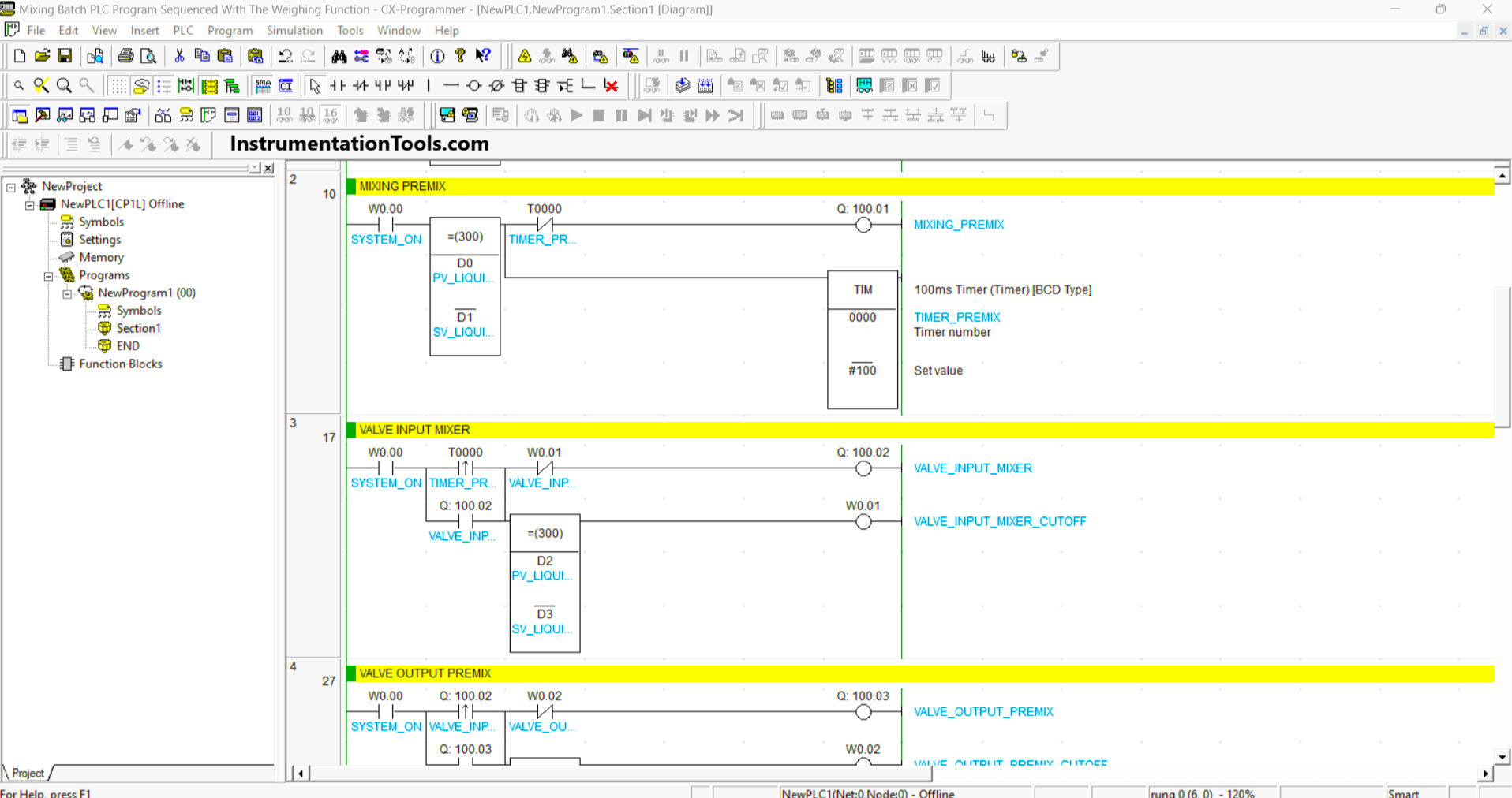
RUNG 3 (MIXER INPUT VALVE)
When NO contacts of the memory bit SYSTEM_ON (W0.00) and TIMER_PREMIX (T0000) are HIGH, the Output VALVE_INPUT_MIXER (100.02) will be OPEN.
When the value in the memory word PV_LIQUID_MIXER (D2) is equal to SV_LIQUID_MIXER (D3) and the memory bit VALVE_INPUT_MIXER_CUTOFF (W0.01) is ON, then the Output VALVE_INPUT_MIXER (100.02) becomes CLOSE because of the “Interlock” of the memory bit VALVE_INPUT_MIXER_CUTOFF (W0.01).
RUNG 4 (VALVE OUTPUT PREMIX)
When NO contacts of the memory bit SYSTEM_ON (W0.00) and VALVE_INPUT_MIXER (100.02) are HIGH, the Output VALVE_OUTPUT_PREMIX (100.03) will be OPEN.
When the memory word PV_LIQUID_PREMIX (D0) is equal to zero “0” and the memory bit VALVE_OUTPUT_PREMIX_CUTOFF (W0.02) is ON, then the Output VALVE_OUTPUT_PREMIX (100.03) becomes CLOSE because of the “Interlock” of the memory bit VALVE_OUTPUT_PREMIX_CUTOFF (W0.02).
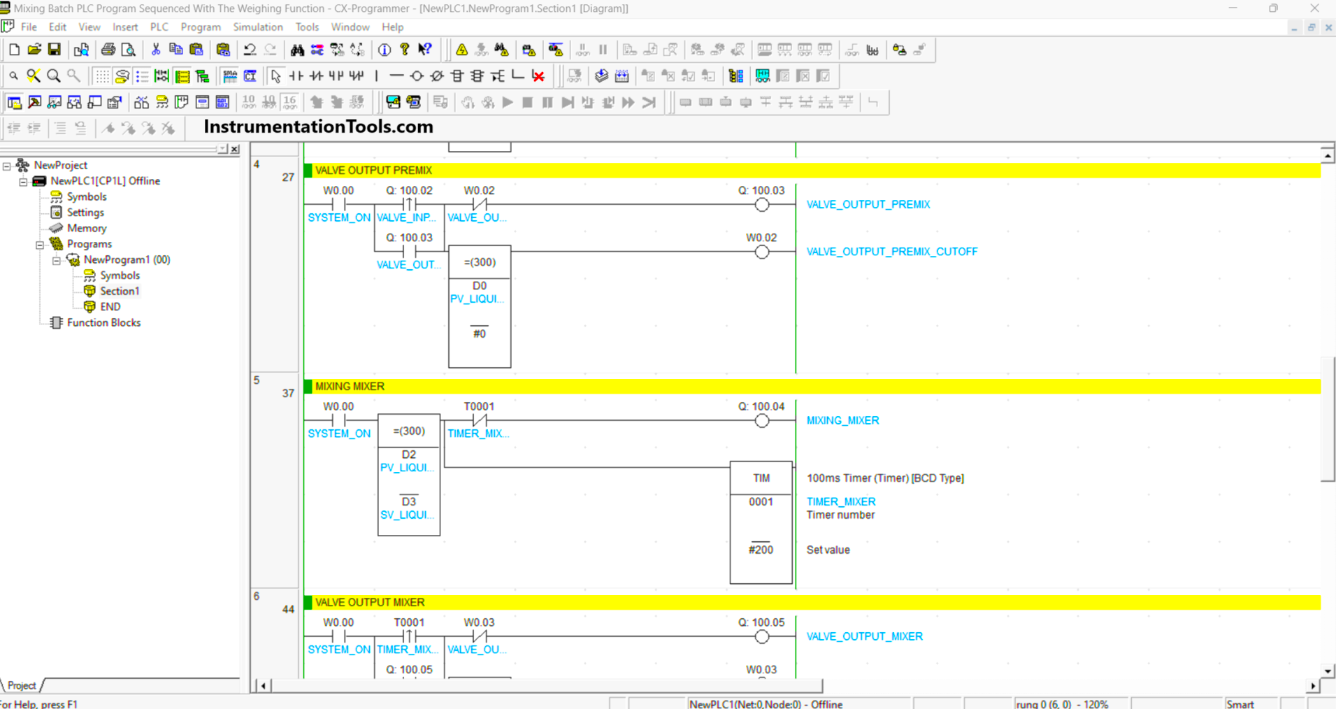
RUNG 5 (MIXING MIXER)
When NO contact of the memory bit SYSTEM_ON (W0.00) is HIGH and the value in the memory word PV_LIQUID_MIXER (D2) is equal to SV_LIQUID_MIXER (D3), then the Output MIXING_MIXER (100.04) will be ON and the Timer TIMER_MIXER (T0001) starts counting up to 20 seconds.
The Output MIXING_MIXER (100.04) will be OFF when the TIMER_MIXER (T0001) Timer reaches “Set value”.
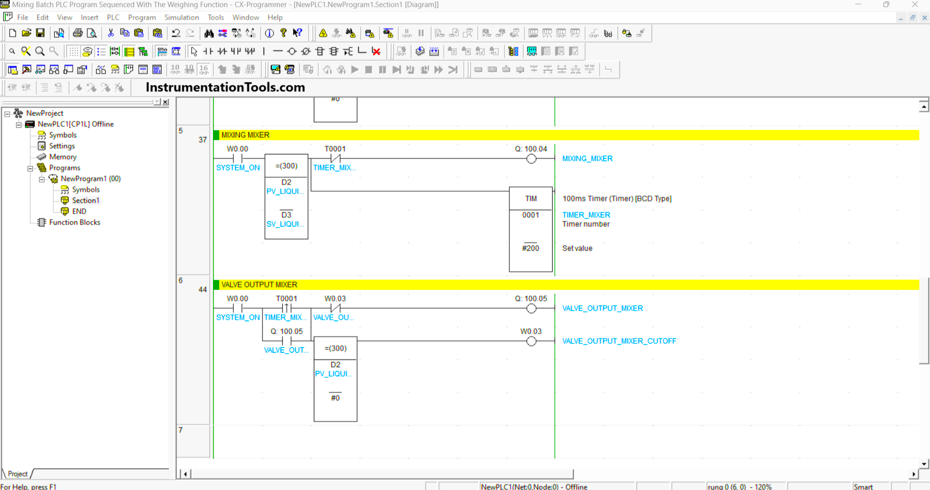
RUNG 6 (MIXER OUTPUT VALVE)
When NO contact of the memory bit SYSTEM_ON (W0.00) and TIMER_MIXER (T0001) is HIGH, the Output VALVE_OUTPUT_MIXER (100.05) will be OPEN.
When the memory word PV_LIQUID_MIXER (D2) is equal to zero “0” and the memory bit VALVE_OUTPUT_MIXER_CUTOFF (W0.03) is ON, then the Output Output VALVE_OUTPUT_MIXER (100.05) becomes CLOSE because of the “Interlock” of the memory bit VALVE_OUTPUT_MIXER_CUTOFF (W0.03).
Read Next:
- PLC Product Sticker Machine with Weighing
- Pump and Mixer Operations PLC Example
- Waste-Burning System Omron PLC Example
- Product Painting with Omron PLC Program
- Schneider PLC Logic for Star-Delta System