Inst ToolsInst ToolsInst Tools
  • Courses
  • Automation
    • PLC
    • Control System
    • Safety System
    • Communication
    • Fire & Gas System
  • Instrumentation
    • Design
    • Pressure
    • Temperature
    • Flow
    • Level
    • Vibration
    • Analyzer
    • Control Valve
    • Switch
    • Calibration
    • Erection & Commissioning
  • Interview
    • Instrumentation
    • Electrical
    • Electronics
    • Practical
  • Q&A
    • Instrumentation
    • Control System
    • Electrical
    • Electronics
    • Analog Electronics
    • Digital Electronics
    • Power Electronics
    • Microprocessor
  • Request
Search
  • Books
  • Software
  • Projects
  • Process
  • Tools
  • Basics
  • Formula
  • Power Plant
  • Root Cause Analysis
  • Electrical Basics
  • Animation
  • Standards
  • 4-20 mA Course
  • Siemens PLC Course
Reading: Schematic Diagram
Share
Font ResizerAa
Inst ToolsInst Tools
Font ResizerAa
  • Courses
  • Design
  • PLC
  • Interview
  • Control System
Search
  • Courses
  • Automation
    • PLC
    • Control System
    • Safety System
    • Communication
    • Fire & Gas System
  • Instrumentation
    • Design
    • Pressure
    • Temperature
    • Flow
    • Level
    • Vibration
    • Analyzer
    • Control Valve
    • Switch
    • Calibration
    • Erection & Commissioning
  • Interview
    • Instrumentation
    • Electrical
    • Electronics
    • Practical
  • Q&A
    • Instrumentation
    • Control System
    • Electrical
    • Electronics
    • Analog Electronics
    • Digital Electronics
    • Power Electronics
    • Microprocessor
  • Request
Follow US
All rights reserved. Reproduction in whole or in part without written permission is prohibited.
Inst Tools > Blog > Electrical Theory > Schematic Diagram

Schematic Diagram

Last updated: July 22, 2018 11:19 pm
Editorial Staff
Electrical Theory
No Comments
Share
1 Min Read
SHARE

Schematic diagrams are the standard means by which we communicate information in electrical and electronics circuits. On schematic diagrams, the component parts are represented by graphic symbols. Because graphic symbols are small, it is possible to have diagrams in a compact form. The symbols and associated lines show how circuit components are connected and the relationship of those components with one another.

Schematic Diagram

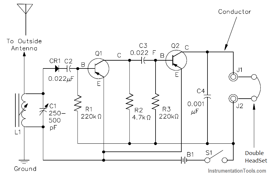
Figure 9 Schematic Diagram

As an example, let us look at a schematic diagram of a two-transistor radio circuit (Figure 9). This diagram, from left to right, shows the components in the order they are used to convert radio waves into sound energy. By using this diagram it is possible to trace the operation of the circuit from beginning to end. Due to this important feature of schematic diagrams, they are widely used in construction, maintenance, and servicing of all types of electronic circuits.

Don't Miss Our Updates
Be the first to get exclusive content straight to your email.
We promise not to spam you. You can unsubscribe at any time.
Invalid email address
You've successfully subscribed !

Continue Reading

AC Generator Theory
Power in Balanced 3 Phase Loads
DC Machines Construction
Classification of Transformers
Apparent Power, True Power, Reactive Power & Total Power
Single Phase Power Wiring Schemes
Share This Article
Facebook Whatsapp Whatsapp LinkedIn Copy Link
Share
Leave a Comment

Leave a Reply Cancel reply

Your email address will not be published. Required fields are marked *

Stay Connected

128.3kFollowersLike
69.1kFollowersFollow
210kSubscribersSubscribe
38kFollowersFollow

Categories

Explore More

Electrical Wiring Terminology
Moving Iron Vane Meter Movement
Ampere Hour Meter
DC Motor Theory
AC Generation
DC Motor Torque
Multimeter & Megger Principle
Magnetic Circuits

Keep Learning

Shunt-Wound DC Motor

Shunt-Wound Motor Operation

Parallel RLC Circuit

Impedance in RLC Circuits

Parallel Circuit Unknown Resistance

Simplified Formulas for Parallel Circuit Resistance Calculations

Squirrel-Cage Induction Rotor

Induction Motor

Series - Wound DC Motor

Series-Wound Motor

Left-Hand Rule for Generators

DC Generator Theory

DC Machine

DC Generator Internal Losses

Generator Action in a Motor

What is Synchroscope ?

Learn More

Control systems in industrial projects

Interactions With Process Control Systems Philosophy

Strain Gauge Pressure Sensor Principle

Strain Gauge Pressure Sensor Principle

Electromagnetic Flow Meters Working Principle

Control Speed of an Induction Motor using Analog Output of PLC

Control Speed of Induction Motor using Analog Output of PLC

Difference Between LED and LDR

Difference Between LED and LDR

Difference Between Sensor and Transducer

What is the Difference Between Sensor and Transducer?

Analog Measurement using Ladder Logic

Analog Measurement using Ladder Logic

Power Electronics Objective Questions

Choppers Quiz

Menu

  • About
  • Privacy Policy
  • Copyright

Quick Links

  • Learn PLC
  • Helping Hand
  • Part Time Job

YouTube Subscribe

Follow US
All rights reserved. Reproduction in whole or in part without written permission is prohibited.
Welcome Back!

Sign in to your account

Username or Email Address
Password

Lost your password?