Learn analog input scaling methods in RSLogix 500 software using Scale with parameters (SCP) and Scale (SCL) instructions.
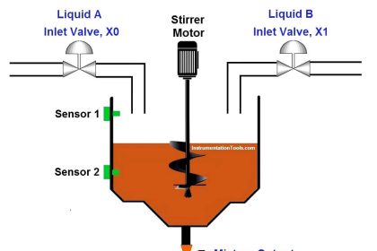
Analog inputs provide a way for us to understand the real-time parameters of the environment around.
Example: Temperature of the surrounding, Humidity in air, Moisture in the air, level of the water in a tank, and speed of the flow of fluids in a plant.
So all these parameters are going to be in a specific unit.
Example: level in liters, pressure in bar, the temperature in degree celsius, and etc.
But all the sensors we use to measure those parameters provide a variable voltage as output that is called Analog inputs to our Automation system.
Each sensor has a specific range of output which you can refer to the sensor manual.
Consider a sensor whose output range is 0 to 10v.
0v being the least and 10v being the maximum value of the sensor measured parameter.
But these values cannot be read into PLC as they occur. All the values that a controller reads will be in digital.
Scaling Analog Input RSLogix 500
For example, an Electronic system reads the number 15 as “1111”.
In this way, Allen Bradley PLC’s read analog voltage values from 0v to 10v as 0 to 4000.
This will be the read digital value by our PLC.
0v <- – – – – – – – – -> 0
2.5v <- – – – – – – -> 1000
5v <- – – – – – – – -> 2000
7.5v <- – – – – – – -> 3000
10v <- – – – – – – – > 4000
However, we want to scale those values accurately to see exactly how much voltage the analog sensor is outputting.
Then we can use the specific unit conversion formulas to display the exact value of the parameter we are measuring.
There are two methods to scale an analog input in RSLogix 500,
- Scale with parameters (SCP)
- Scale (SCL)
Scale with Parameters (SCP)
In scale with parameters (SCP), there are the following specifics to be mentioned,
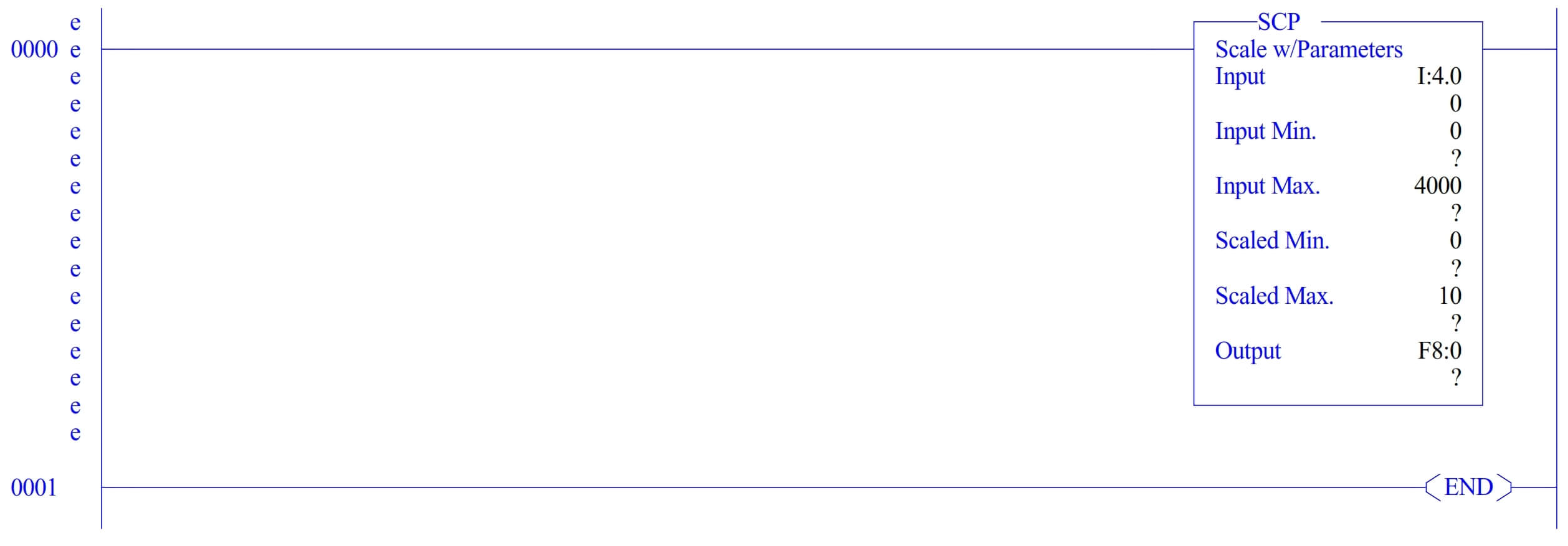
- Input – where you have to give the address of the input which is acquiring the analog sensor’s output voltage.
- Input Min – where you have to specify the minimum digital value received. In this case, our minimum value is 0.
- Input max – where you have to specify the maximum digital value received. In this case, our maximum value is 4000.
- Scaled Min – Where you have to specify the minimum value of the range you want to scale. In this case, our scaled minimum is 0v.
- Scaled Max – where you have to specify the maximum value of the range you want to scale. In this case, our scaled maximum is 10v.
- Output – where you have to give an address to output the scaled value. You can give a float or integer address in here. However, Float will give you the most accurately scaled value.
Scale (SCL)
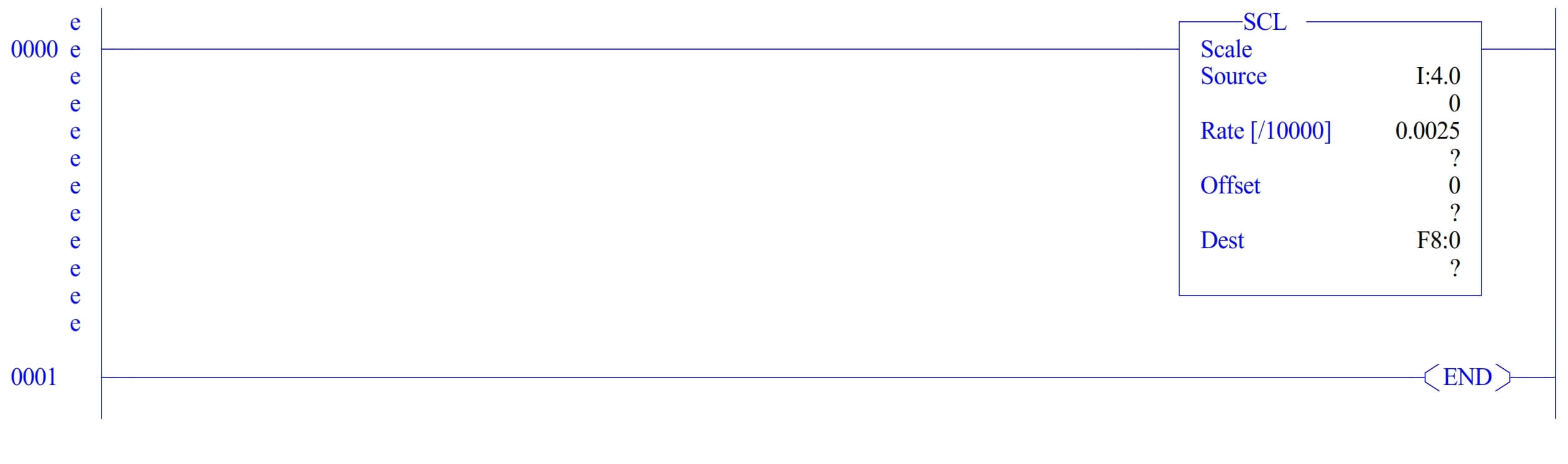
In scale (SCL) there are the following specifics to be mentioned,
- Source – where you have to specify the source address where the analog value is read.
- Rate – Here is the formula for it Rate = (scaled max. – scaled min.) / (input max. – input min.) in our case the value of rate will be 0.0025.
- Offset- whenever your sensor output value is wrong and it displays 6v in the place of 7v you can add 1 to offset to correct the error.
- Dest – The same as before, here you can give a float or integer address to save the scaled value.
- This will be the formula for scaled output. Scaled value = (input value x rate) + offset
Author: Abishek D
If you liked this article, then please subscribe to our YouTube Channel for PLC and SCADA video tutorials.
You can also follow us on Facebook and Twitter to receive daily updates.
Read Next:
- Flow Transmitter Scaling in PLC
- Masked Move Instruction
- Retentive ON Delay Timer
- Measurement using PLC Logic
- PLC Arithmetic instructions