Safety systems are implemented to reduce operational risks and improve process safety; however, there are instances when some signals of this system shall be bypassed or overridden (see the reference articles). There are some different ways to implement such a goal from the beginning/ source of the signal (at the sensor) up to the implemented point in functional logic. This article tries to review some of these ways and compare them for their benefits and deficiencies.
Safety Signal Bypass

Figure 1: Different Types of Applying Safety Signal Bypass and Override
Bypassing Safety Signal via Hardware or Software
Safety Signal Inputs come to the Functional Logics through passing different stages from the Initiator (sensor) point up to the action point in the logic. The main stages, as shown in Figure 1, can be considered as:
Sensor/Initiator point, Field junction Box, Marshalling Cabinet Connection, System I/O Database, and finally action point in the Functional Logics.
Bypassing or overriding safety signals can be done in each of the above-mentioned stages, and as it can be seen from Figure 1, it may be done in two main modes: By Hardware or via Software. Although using software mode may include some (other) hardware input conditions too (as it will be reviewed later).
It shall be mentioned here that Figure 1 is applicable for all (digital) processing Control and Safety Systems (like DCS, ESD/SIS, PLC, Controllers …), but we are focusing on using it in this article just for safety systems (which have very critical/ important roles in Industrial Process Plants).
In addition, it shall be mentioned that, nowadays using just hardware mode for bypassing safety signals has been (approximately) abolished, and is reviewed in this article just to be familiar with different ways used for bypassing and find better the benefits of common, usual today ways (with main concern on software functionality).
Now, by making explanations, let us review different ways of bypassing safety signals in more detail.
Jumper at Field Instrument
The more risky way for bypassing the safety signal is using the jumper (the signal) at the field instrument point. Since the safety signal is usually considered as a fail-safe, and hence the “1” or “closed contact” signal is considered as the normal state, usually bypassing the signal is equal to jumper or short circuit connection at the end terminal (see Figure 2). Although the negative bypassing (force signal to zero state) is possible by making an open circuit at the end terminals. It is clear that this way of bypassing is applicable for switch-type signals (such as Pressure Switch, Temperature Switch, Flow Switch …), and bypassing analog transmitter signals is not so easy, will be very complicated, and is usually not used. On the other hand, this way of Bypassing is applicable mainly for switches (Digital Input) signals.

Figure 2: Field Instrument (Switch) Signal Bypass by using Jumper Wire
In this way of bypassing the signal, the safety system will be blind regarding the bypass, and no feedback indication or relevant alarm can be produced to alert the operators. Furthermore, there is no feedback from the actual process signal, and the system will assume a continuous normal state for the process signal (as the jumper existed). Due to poor (nothing) information for bypass job in the safety system, accordingly, there is no possible documentation or automatic job/ risk-tracing facility will be possible via the Safety System.
In fact, this type of bypassing the signal needs maximum administrative controls and procedural activities via site personnel, and it has a significant amount of safety risks.
Administrative controls include a set of regular activities and communications by considering the site position responsibilities, further to relevant paper documentations (like Lock Out Tag Out (LOTO) and Permit To Work).
In addition, it shall be noticed that due to some possible (critical) site conditions (environment), this type of bypassing is not applicable (due to poor accessibility) for some sensors during Process Plant Operation, by site specialists.
If the target of bypassing signal is device proof testing, this type of bypassing may not be applicable, and furthermore, making the jumper during the normal state of the instrument may produce an instantly faulty (open) signal and may increase the spurious shutdown to the Process Plant Operation.
Generally, this type of bypassing has huge risks and can be considered the worst case, and it is not recommended strictly.
Hardwired Jumper at Termination Point Terminals
This type of bypass may be applicable to terminals at the Field Junction Box or even on the terminals of the input section of the Marshalling Cabinets of the Safety System.
This type of bypassing the signal is similar to a jumper at field instruments, while some of the weaknesses, like device proof testing, checking the real state of the instrument signal, and access problems for doing the job, are covered.
However, in these types of bypassing the signal, the Safety System is blind to the activity of bypassing too, and so there is no automatic tracing or system documentation available, and they need exact administrative controls.
These types of hardwired bypassing may be done in different ways, while Figures 3 and 4 show two common ways in this regard. As figures show, the bypassed point may not be clear at quick glance and needs exact investigation. In fact, twisting the signal wires may be missed behind the crowded/ condensed wires, and direct twisting of the wires without any cover may cause a short circuit between system powers and any grounded metallic parts or enclosures, and hence may produce system power cut-off and, accordingly, process plant shutdown.
Due to the mentioned negative points, such bypassing ways are not used nowadays either.
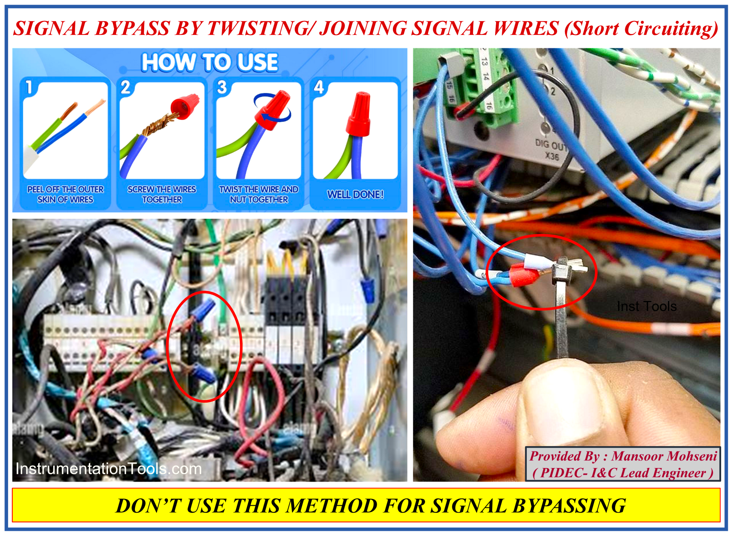
Figure 3: Signal Bypass by Twisting/ Joining Signal Wires.
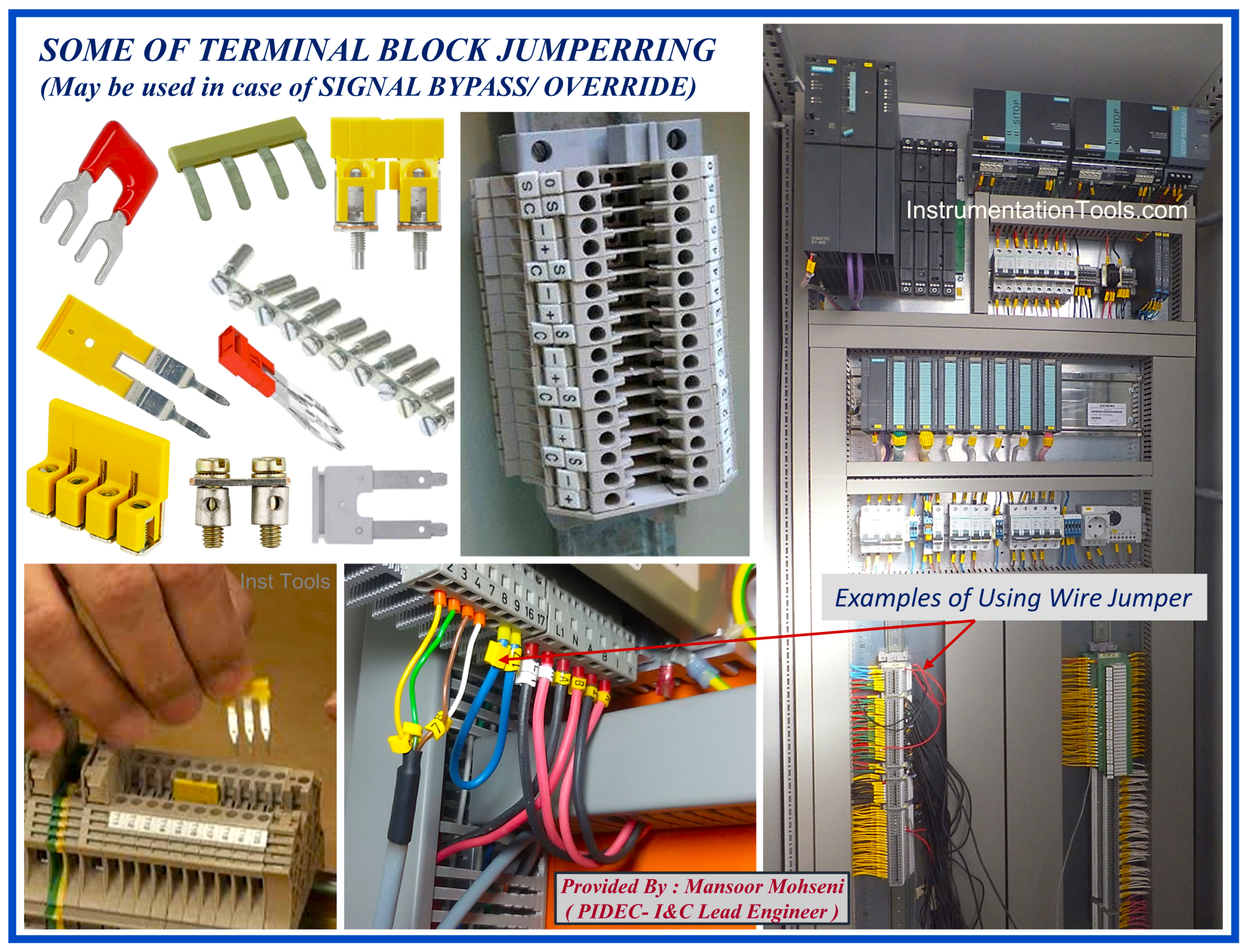
Figure 4: Signal Bypass via Jumper on Terminal Block.
Bypass by Using a Selector Switch at the Input Panels
By inserting the Selector Switches in the system input hardwired connection, the input signal will be bypassed by regular, clean, clear, and fast pre-connected circuits (/ relays), and so it covers some weaknesses of the mentioned hardware jumpers. Figure 5 shows a sample of using selectors for bypassing the signal.
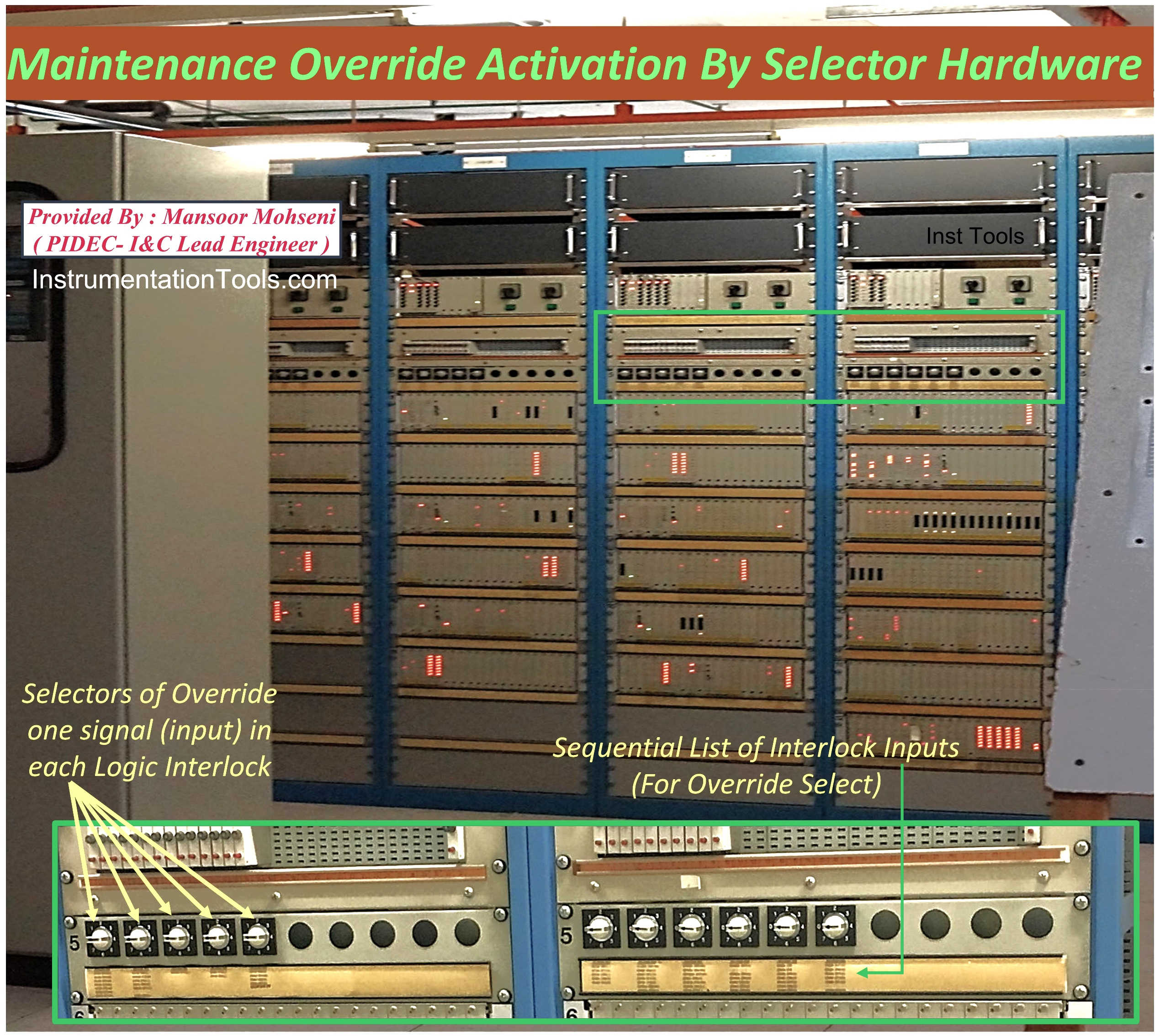
Figure 5: Using Selector Hardware for Bypassing the Signal.
Due to the critical importance of making fewer changes to safety configurations, further to space limitations (for inserting one selector on each input), as Figure 5 shows, one selector is considered for a group of interlock inputs. On the other hand, in this way, just one input of each group of inputs (to interlock) can be bypassed (although the bypassing will occur after selecting the input and then connecting the power supply to the input of the selector switch, as enabled). This type of hardware bypassing is regulated, fast, and standard way, but still in this way, the Safety System will be blind to the Bypass job, and needs exact administrative controls.
If the outputs of selector signals (without any additional relays) connected to Safety System Inputs and were combined with each input of interlock, inside the logic diagram, it would reach nearly to nowadays bypassing routine (as we see in the following). Figure 5 may even be implemented for this type of Bypassing.
Bypass by Forcing the Input Signal at the Database
This type of Bypass is purely made via software, in which the I&C Engineer will change the considered register for the value of the subject input by forcing to set value. This Bypass type can be applicable for digital or analog input, and may indicate bypass and special alarms inside the Engineering Workstation of the Safety System. Although in this type of Bypassing, the actual value of the Process Signal can be monitored in the Engineering Workstation (for finding the signal healthiness), the Process Plant Operator will not be informed directly regarding the bypassing. On the other hand, the Control & Safety System cannot produce complete documentation and job tracing for the Bypassed Signal.

Figure 6: IEC 61511 Standard restricted the use of Bypass via Forcing.
IEC 61511 restricted the use of Bypass by forcing except under some conditions. In fact, bypassing or overriding the signals for some signals without consideration of Maintenance Override Switches (inside the application program) is not possible except by forcing.
Also, in plant startup, in which some operations or process/ equipment mode testing can be done just by multiple overriding (bypassing) signals, using the Forcing routine may be just the available way of Bypassing (considering IEC 61511 restricted conditions).
Bypass via Maintenance Override Switch (MOS)
The Maintenance Override Switch (MOS) bypass is done through the Safety System Application Program and by using some Maintenance Override Switches (MOS) and enabling conditions. There are different ways for applying this type of Bypassing (even via using Hardware or Software Switches and possible security and tracing), but the main requirements of such Bypassing are mentioned in the IEC-61511 standard.
Usually, in the MOS type of Bypassing, one hardwired (key) switch on the Safety System Hardwired Console will enable the Bypassing of input signals of one interlock, and then the I&C Engineer, through the Safety System or Process Control System Engineering Workstation (or even by secured provided HMI pages), will request the override of the subject input. This request will be processed (check for applicability) in the application program, and in the case of acceptance, Override will be activated and recorded by suitable alarms and indications for further tracing by Control and Safety Systems facilities (like alarm management and log recording). This type of Bypassing is applicable for both Digital and analog input Signals.
Figures 7 and 8 show a sample of the provided MOS Enable Hardwired Switches (on the hardwired Console) and the Relevant HMI Graphic page for monitoring the statuses.

Figure 7: Sample of MOS Enable Switches on Hardwired Console for each Safety System Interlock.
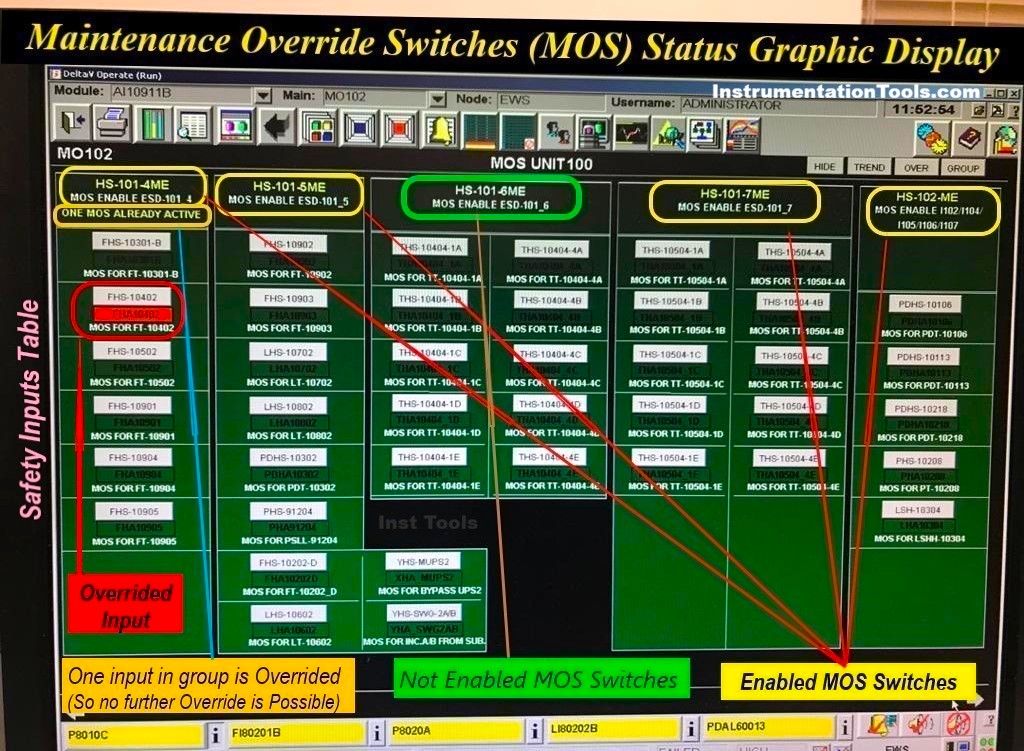
Figure 8: Sample of Graphic Display Page for Monitoring Override Status of Safety System Inputs
For a small process (or unit) project with limited I/O, instead of applying request by I&C Engineer through above mentioned items, Override Request may be done also via separate hardwired (key) switches (for each input/ device) or Interlock Selectors (as we found above) further to MOS Enable (key) Switches (but with good security protections). However, for a medium-scale process project due to physical space limitations, just the MOS Enable of each Interlock will be considered on the Hardwired Console (with above mentioned I&C actions).
For a big Process plant project with a great amount of I/O, limited MOS enable switches are considered on the Hardwired Console just for Process Units (Groups of Interlocks). Notice that, even if all process interlocks can be considered as relevant to one unit, just one MOS Enable Switch may be considered. In any mentioned cases, authentication checks and further administrative controls will be applied for authorisation security checks on applying an override of safety signals.
Let us have a more detailed investigation into this type of Bypassing/overriding.
As mentioned above, this type of Bypassing/overriding is applicable for both digital and analog signals.
This type of bypassing doesn’t cut the hardware connection of the input signal to the Safety System and will have effects on the action of input signals in Functional Safety Logics. Hence, at the same time as Bypass activation, continuous monitoring of real actual value of the input signal in Process Control System (by the Process Operator) will be continued.
In addition, since the bypassing function will occur inside the application program, Bypass Status Alarms and Indications may be easily produced and will be available inside the combined Process and Safety Systems with relevant HMI. This will help the process operators to easily trace the Bypass job status and make proper documentation via the combined Process and Safety Systems facilities.
Nowadays, bypassing the safety signals is done mainly by this type, but it should be noticed that due to project scale size, facilities of Combined Process and Control Systems, Process Safety/ Risk Analysis Conditions, and Engineering Design Practices, it can be done in different ways. (Studying one article for applying good actual practice may be helpful for finding different aspects of this type of Bypassing).
Bypass Management System
Bypass Management System is part of Process Safety Management System (or may be part of the Management Of Change element of PSM) that focuses on making Bypassing jobs in the Process Plant. This system will use Bypassing/ Override Facilities provided by Combined Process and Safety Systems (as explained above), further to complete managing tools and administrative controls for improving the performance and safety of Bypassing Jobs. It may include an additional dedicated computerised (management) system or may use additional management systems implemented in Combined Process Control and Safety Systems.
By such facilities and tools, all bypasses made will be automatically recorded and documented exactly for each device (or equipment) history with exact tag number, date (including Enable/ Disable and Duration Time), and responsible executers and may be traced to the exact events and activities. One of the important outputs of such a system will be critical Reminder Alerts and Alarms or even required actions (in the worst case, it may include process plant operation stop/ shutdown).
Bypass Management System includes some administrative controls like plans and schedules, procedures, sequence charts, competency control management, training courses and materials, communications, signs and indications, and so on.
Conclusion
Bypassing safety signals can be done in different ways through the instrument (sensor) source of signal, up to the final actions inside the logic. Hardware, some by software, and some of them implemented by using both software and hardware. In this article, we reviewed some of these ways, and the comparison results are reflected in Figure 9.

Figure 9: Comparison Results on Types of Applying Signal Bypass/ Override
References:
- Safety Function Bypass or Override
- IEC 61511 Standard for Bypass & Override
- Force Versus Override for Safety Signal Bypass
- A Good Practice on Override Safety Signal
- Safety Bypass Management System