The international standard IEC/EN 61508 has been widely accepted as the basis for the specification, design and operation of safety instrumented systems (SIS).
As the basic standard, IEC/EN 61508 uses a formulation based on risk assessment: An assessment of the risk is undertaken and on the basis of this the necessary Safety Integrity Level (SIL) is determined for components and systems with safety functions.
SIL-evaluated components and systems are intended to reduce the risk associated with a device to a justifiable level or “tolerable risk”.
To categorise the safety integrity of a safety function the probability of failure is considered – in effect the inverse of the SIL definition, looking at failure to perform rather than success.
It is easier to identify and quantify possible conditions and causes leading to failure of a safety function than it is to guarantee the desired action of a safety function when called upon.
Two classes of SIL are identified, depending on the service provided by the safety function.
In summary, IEC/EN 61508 requires that when safety functions are to be performed as specified in terms of a safety integrity level.
The probabilities of failure are also considered in safety integrity levels, as shown

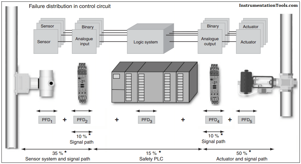
The PFD value (Probability of Failure on Demand) is the probability of failure of a unit as a component part of a complete safety system in the low demand mode.
The PFD value for the complete safety related function is derived from the values of individual components. Sensor and actuator are fitted in the field, leading to exposed and physical stress factors (process medium, pressure, temperature, vibration, etc.).
The risk of failure associated with these components is thus relatively high. 25 % of the entire PFD should be therefore reserved for the sensor, 40 % for the actuator.
15 % remains for the fail-safe control, and 10 % for each of the interface modules (interface modules and the control system have no contact with the process medium and are located in protected switch rooms).
In this article, a simple example will teach you the conversion from Boolean algebra to…
In this article, you will learn the PLC cooking timer example for kitchen automation using…
Learn an example PLC program to control a pump based on level sensors using ladder…
In the PLC timer application for security camera recording, when motion is detected then camera…
In this example, we will learn batch mixing with PLC ladder logic program using timer…
This PLC example on manufacturing line assembly is an intermediate-level PLC program prepared for the…
View Comments
Please give us analysis on the below two questions
What is the significant use of SIS supporting tools in the SIS design stage?
What are the already available SIS supporting tools and what is their main functionality?
You might check out http://www.sissuite.com.
Hi!
There is a confusion in your following text: "for safety function that are in place continuously the probability of a dangerous failure is expressed in terms of a given period of time (per hour)".
A probability is never expressed per time unit. A probability is unitless.
In a continous mode, the used criteria (PFH) is a frequency of failure and not a probability. By the way, the wrong term "probability of failure per hour" does not appear anymore in the second edition of the IEC 61508, because it was inappropriate.
Regards