Inst ToolsInst ToolsInst Tools
  • Courses
  • Automation
    • PLC
    • Control System
    • Safety System
    • Communication
    • Fire & Gas System
  • Instrumentation
    • Design
    • Pressure
    • Temperature
    • Flow
    • Level
    • Vibration
    • Analyzer
    • Control Valve
    • Switch
    • Calibration
    • Erection & Commissioning
  • Interview
    • Instrumentation
    • Electrical
    • Electronics
    • Practical
  • Q&A
    • Instrumentation
    • Control System
    • Electrical
    • Electronics
    • Analog Electronics
    • Digital Electronics
    • Power Electronics
    • Microprocessor
  • Request
Search
  • Books
  • Software
  • Projects
  • Process
  • Tools
  • Basics
  • Formula
  • Power Plant
  • Root Cause Analysis
  • Electrical Basics
  • Animation
  • Standards
  • 4-20 mA Course
  • Siemens PLC Course
Reading: Root Cause Analysis for FRP Line Damaged due to On-Off Valve
Share
Notification Show More
Font ResizerAa
Inst ToolsInst Tools
Font ResizerAa
  • Courses
  • Design
  • PLC
  • Interview
  • Control System
Search
  • Courses
  • Automation
    • PLC
    • Control System
    • Safety System
    • Communication
    • Fire & Gas System
  • Instrumentation
    • Design
    • Pressure
    • Temperature
    • Flow
    • Level
    • Vibration
    • Analyzer
    • Control Valve
    • Switch
    • Calibration
    • Erection & Commissioning
  • Interview
    • Instrumentation
    • Electrical
    • Electronics
    • Practical
  • Q&A
    • Instrumentation
    • Control System
    • Electrical
    • Electronics
    • Analog Electronics
    • Digital Electronics
    • Power Electronics
    • Microprocessor
  • Request
Follow US
All rights reserved. Reproduction in whole or in part without written permission is prohibited.
Inst Tools > Blog > Root Cause Analysis (RCA) > Root Cause Analysis for FRP Line Damaged due to On-Off Valve

Root Cause Analysis for FRP Line Damaged due to On-Off Valve

Root Cause Analysis for FRP line damaged due to On-Off Valve operation due to high instrument air pressure to the actuator.

Last updated: October 3, 2022 4:35 pm
Editorial Staff
Root Cause Analysis (RCA) Control Valves
1 Comment
Share
4 Min Read
SHARE

An FRP line was continuously getting damaged (cracks were observed). This was occurring very frequently (once per 15 to 20 days).

Contents
On-Off Valve ProblemOn-Off Valve Root Cause AnalysisObservations

On-Off Valve Problem

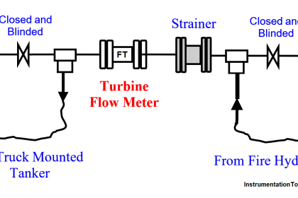
An FRP line was installed in one plant for supplying water to a mixing tank. The line size was 10 inches. An On-Off valve, an isolation valve, a pressure transmitter, and a flow transmitter were installed in the same line. Almost after every 15 to 20 days, the FRP line got damaged near the On-Off valve.

So, what can be the probable reason for frequent damage to the FRP line?

On Off Valve Root Cause Analysis

On-Off Valve Root Cause Analysis

Probable Problem 1: FRP line not having proper supports 

FRP line was installed as per standard and sufficient support was also provided.

Probable Problem 2: FRP line might be thin as compared to the standard / required thickness

FRP thickness verified with standard documents. FRP line thickness was perfect. 

Probable Problem 3: High vibrations in FRP line

No vibrations were observed in the FRP line while the water was passing through the line.

Probable Problem 4: High pressure of water flowing through the FRP line.

The pressure of the water is confirmed through the pressure transmitter. The pressure was below maximum operating pressure.

The standard operating pressure was 6 kg/cm2 while the maximum pressure observed during the feed inlet to the tank was 2.8 kg/cm2 due to the unavailability of one out of three feed pumps.

Probable Problem 5: Design issue in the line size and On-Off valve sizing

Design side all parameters reverified with the vendor. All sizing found ok.

Observations

Observations after frequent visits to the FRP line during different timings:

During normal operations, the FRP line was very steady like all other lines in the plant. But, whenever the On-Off valve was given close command, the valve got operated by creating a heavy sound.

So, on continuous observation of the valve, it was found that the valve is the main root cause of the FRP pipe getting damaged.

What went wrong?

On further checking by the Instrumentation team, the Instrument air pressure to the On-Off valve was found 6.5 kg/cm2.

(Some basic information:  The on-off valve is having a butterfly-type body. The on-Off valve size is 8 inches.

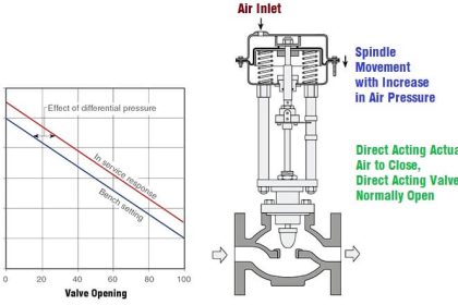
Also, the fail action of the valve is fail-open.  So, the air is required to close the valve. As per the datasheet, Instrument Air pressure to the actuator should be a maximum of 4.5 kg/cm2)

The instrumentation team checked the operation of the valve with 6.5 kg/cm2 air pressure and found that the valve movement during the closing time was very fast. This also caused very high vibration and jerks during closing.

So, after a detailed study, it was concluded that there are 2 main reasons for this FRP line getting damaged

  1. On-Off valve operation during close command was damaging the line which is due to high Instrument Air Pressure to the actuator.
  2. Already the pressure of the water in the line was low i.e. 2.8 kg/cm2 as compared to the standard 6 kg/cm2 pressure. This was due to the unavailability of a feed pump. Hence this condition also amplified the damage caused by the On-Off valve movement.

Immediately, the Instrument Air pressure to the On-Off valve was normalized to 4.5 kg/cm2. Also, this point was included in LLF to check the Instrument Air pressure of all valves.

Don't Miss Our Updates
Be the first to get exclusive content straight to your email.
We promise not to spam you. You can unsubscribe at any time.
Invalid email address
You've successfully subscribed !

Continue Reading

Condensate Pump Frequent Wrecks Threatens Long Plant Outages
Alternate 110 KV Connection to Feeder A
What is a Servo Valve? – Principle and Advantages
How to Install a Control Valve?
Serious Constraints Prevent using an Available Turbine Flow Meter
Pressure Relief Valve Terminology
Share This Article
Facebook Whatsapp Whatsapp LinkedIn Copy Link
Share
1 Comment
  • power systems says:
    October 7, 2022 at 10:09 am

    very good and useful infomation

    Reply

Leave a Reply Cancel reply

Your email address will not be published. Required fields are marked *

Stay Connected

128.3kFollowersLike
69.1kFollowersFollow
210kSubscribersSubscribe
38kFollowersFollow

Categories

Explore More

Refrigeration Compressor Turbine Not-tripping when needed Trip
PID Controller Action : Directing Acting & Reverse Acting
Difference Between Linear Actuator and Rotary Actuator
What is Double-ported Globe Valve ?
Four Way Solenoid Valve Working Principle
Control Valve Packing
Basics of Valves Interview Questions & Answers
Poor Electrical Heating Element Lives – Problem Solved

Keep Learning

Safety Relief Valve

Safety Relief Valve Quiz: Test Your Knowledge

Globe Control Valve Animation

Basics of Globe Valves

Control Valves Leak Tightness

Control Valves Leak Tightness Restoration Pose Difficulties

Digital Control Valve Working Principle

Digital Control Valve Working Principle

Summary of Valve Types Characteristics

Summary of Valve Types Characteristics

Valve Diaphragm Actuator

Spring and Diaphragm Pneumatic Actuators

Two SOV Connections

Two Solenoid Valves Working Principle

Direct operated (direct acting) solenoid valves

Solenoid Valves Types & Functions

Learn More

Roller Conveyor

Difference Between Belt Conveyor and Roller Conveyor

Instrument System Architecture and Process Control Design

System Architecture and Process Control Systems Philosophy

Siemens SIMATIC S7 PLC GSD File

How to import GSD files into the TIA Portal? – Siemens PLC

Optical Modulation

What is Optical Modulation? – Methods of Optical Modulation

Photo Electric Transducers Objective Questions

Photo Electric Transducers Objective Questions

PLC Programming Questions

PLC Programming Question & Answer

Fire Alarm System Commissioning Procedure

Fire Alarm System Commissioning Procedure

Safety interlock for motor starters in Siemens PLC

Motor Starter Logic using Siemens PLC Tia Portal

Menu

  • About
  • Privacy Policy
  • Copyright

Quick Links

  • Learn PLC
  • Helping Hand
  • Part Time Job

YouTube Subscribe

Follow US
All rights reserved. Reproduction in whole or in part without written permission is prohibited.
Welcome Back!

Sign in to your account

Username or Email Address
Password

Lost your password?