Inst ToolsInst ToolsInst Tools
  • Courses
  • Automation
    • PLC
    • Control System
    • Safety System
    • Communication
    • Fire & Gas System
  • Instrumentation
    • Design
    • Pressure
    • Temperature
    • Flow
    • Level
    • Vibration
    • Analyzer
    • Control Valve
    • Switch
    • Calibration
    • Erection & Commissioning
  • Interview
    • Instrumentation
    • Electrical
    • Electronics
    • Practical
  • Q&A
    • Instrumentation
    • Control System
    • Electrical
    • Electronics
    • Analog Electronics
    • Digital Electronics
    • Power Electronics
    • Microprocessor
  • Request
Search
  • Books
  • Software
  • Projects
  • Process
  • Tools
  • Basics
  • Formula
  • Power Plant
  • Root Cause Analysis
  • Electrical Basics
  • Animation
  • Standards
  • 4-20 mA Course
  • Siemens PLC Course
Reading: Reliability of a Control System
Share
Font ResizerAa
Inst ToolsInst Tools
Font ResizerAa
  • Courses
  • Design
  • PLC
  • Interview
  • Control System
Search
  • Courses
  • Automation
    • PLC
    • Control System
    • Safety System
    • Communication
    • Fire & Gas System
  • Instrumentation
    • Design
    • Pressure
    • Temperature
    • Flow
    • Level
    • Vibration
    • Analyzer
    • Control Valve
    • Switch
    • Calibration
    • Erection & Commissioning
  • Interview
    • Instrumentation
    • Electrical
    • Electronics
    • Practical
  • Q&A
    • Instrumentation
    • Control System
    • Electrical
    • Electronics
    • Analog Electronics
    • Digital Electronics
    • Power Electronics
    • Microprocessor
  • Request
Follow US
All rights reserved. Reproduction in whole or in part without written permission is prohibited.
Inst Tools > Blog > Safety Instrumented System (SIS) > Reliability of a Control System

Reliability of a Control System

Last updated: March 22, 2019 10:51 am
Editorial Staff
Safety Instrumented System (SIS)
No Comments
Share
6 Min Read
SHARE

Reliability (R) is the probability a component or system will perform as designed. Like all probability figures, reliability ranges in value from 0 to 1, inclusive.

Reliability of a Control System
Reliability of a Control System

Given the tendency of manufactured devices to fail over time, reliability decreases with time. During the useful life of a component or system, reliability is related to failure rate by a simple exponential function:

R = e−λt

Where,

R = Reliability as a function of time (sometimes shown as R(t))
e = Euler’s constant (≈ 2.71828)
λ = Failure rate (assumed to be a constant during the useful life period)
t = Time

Knowing that failure rate is the mathematical reciprocal of mean time between failures (MTBF), we may re-write this equation in terms of MTBF as a “time constant” (τ ) for random failures during the useful life period:

R = e−t/MTBF       or         R = e−t/λ

This inverse-exponential function mathematically explains the scenario described earlier where we tested a large batch of components, counting the number of failed components and the number of surviving components over time.

Like the dice experiment where we set aside each “failed” die and then rolled only the remaining “survivors” for the next trial in the test, we end up with a diminishing number of “survivors” as the test proceeds.

The same exponential function for calculating reliability applies to single components as well. Imagine a single component functioning within its useful life period, subject only to random failures.

The longer this component is relied upon, the more time it has to succumb to random faults, and therefore the less likely it is to function perfectly over the duration of its test.

To illustrate by example, a pressure transmitter installed and used for a period of 1 year has a greater chance of functioning perfectly over that service time than an identical pressure transmitter pressed into service for 5 years, simply because the one operating for 5 years has five times more opportunity to fail. In other words, the reliability of a component over a specified time is a function of time, and not just the failure rate (λ).

Using dice once again to illustrate, it is as if we rolled a single six-sided die over and over, waiting for it to “fail” (roll a “1”). The more times we roll this single die, the more likely it will eventually “fail” (eventually roll a “1”). With each roll, the probability of failure is 1/6 , and the probability of survival is 5/6 .

Since survival over multiple rolls necessitates surviving the first roll and and next roll and the next roll, all the way to the last surviving roll, the probability function we should apply here is the “AND” (multiplication) of survival probability.

Therefore, the survival probability after a single roll is 5/6 , while the survival probability for two successive rolls is ( 5/6)2 , the survival probability for three successive rolls is  (5/6)3 , and so on.

The following table shows the probabilities of “failure” and “survival” for this die with an increasing number of rolls:

Control System probabilities of failure and survival

A practical example of this equation in use would be the reliability calculation for a Rosemount model 1151 analog differential pressure transmitter (with a demonstrated MTBF value of 226 years as published by Rosemount) over a service life of 5 years following burn-in:

R = e−5/226

R = 0.9781 = 97.81%

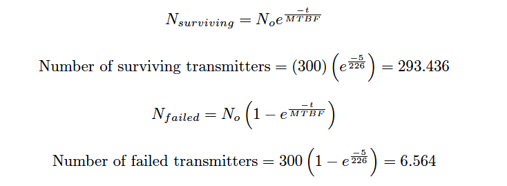
Another way to interpret this reliability value is in terms of a large batch of transmitters. If three hundred Rosemount model 1151 transmitters were continuously used for five years following burn-in (assuming no replacement of failed units), we would expect approximately 293 of them to still be working (i.e. 6.564 random-cause failures) during that five-year period:

Instrument Transmitters Failure

It should be noted that the calculation will be linear rather than inverse-exponential if we assume immediate replacement of failed transmitters (maintaining the total number of functioning units at 300).

If this is the case, the number of random-cause failures is simply 1/226 per year, or 0.02212 per transmitter over a 5-year period. For a collection of 300 (maintained) Rosemount model 1151 transmitters, this would equate to 6.637 failed units over the 5-year testing span:

Number of failed transmitters = (300) ( 5/226) = 6.637

Articles You May Like :

IEC 61511 Standard

Failure Rate Calculation

Burner Management System

Maintenance Override Switch

Layers of Protection Analysis

Don't Miss Our Updates
Be the first to get exclusive content straight to your email.
We promise not to spam you. You can unsubscribe at any time.
Invalid email address
You've successfully subscribed !

Continue Reading

SIS Final Control Elements
SIS Application Program – Safety Instrumented System
Intrinsic Safe Calculation
What is Maintenance Override Switch (MOS) ?
Basic Terms used in SIL Verification
SIS Software Simulation – Safety Instrumented System
Share This Article
Facebook Whatsapp Whatsapp LinkedIn Copy Link
Share
Leave a Comment

Leave a Reply Cancel reply

Your email address will not be published. Required fields are marked *

Stay Connected

128.3kFollowersLike
69.1kFollowersFollow
210kSubscribersSubscribe
38kFollowersFollow

Categories

Explore More

What is Burner Management System (BMS)?
Transmitter Proof Testing
Safety Instrumented System (SIS) Worksheets and Documents
What is High Integrity Pressure Protection System?
BPCS Control System and ESD Safety System of Delta-V DCS
Energize to Safe Loop philosophy
Understanding Safety Integrity Level IEC 61511
Understanding Emergency Shutdown Button Installation (ESD)

Keep Learning

Emergency Block Valve

SIS Emergency Block Valves (EBV)

LAYERS OF PROTECTION ANALYSIS

Layers of Protection Analysis (LOPA) Interview Questions

ESD System Insights

ESD System Insights: Signals for Emergency Valve Shutdown Explained

Safety PLC System

SIS Maintenance – Safety Instrumented System

Safety Integrity Level (SIL)

Emergency ShutDown Valve Working Principle

ESDV : How it Works ?

Difference between SIS, PLC and BPCS Systems

Difference between SIS, PLC and BPCS Systems

transmitters shared for BPCS and SIS

SIS Instrument Sharing – Transmitters Shared for BPCS and SIS Example

Learn More

PLC Software Redundancy

Software Redundancy in Siemens PLC – Hardware versus Software

Industrial Automation and Control Interview Questions

Industrial Automation and Control Interview Questions

Temperature Switch Symbol

Temperature Switch Principle

Power Electronics Objective Questions

Pulse Width Modulation Inverters Questions

Power System Protection Multiple Choice Questions

Power System Protection Multiple Choice Questions

Difference Between RS232 and RS485

Difference Between RS232 and RS485

Difference Between Static and Temp Memory in Siemens TIA Portal

Difference Between Static and Temp Memory in Siemens PLC TIA Portal

Types of Capacitors

Types of Capacitors

Menu

  • About
  • Privacy Policy
  • Copyright

Quick Links

  • Learn PLC
  • Helping Hand
  • Part Time Job

YouTube Subscribe

Follow US
All rights reserved. Reproduction in whole or in part without written permission is prohibited.
Welcome Back!

Sign in to your account

Username or Email Address
Password

Lost your password?