Basic Relay Circuit :
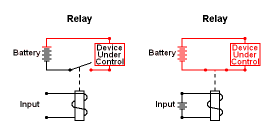
Relays are switches that open and close circuits electromechanically or electronically. Relays control one electrical circuit by opening and closing contacts in another circuit.
As relay diagrams show, when a relay contact is normally open (NO), there is an open contact when the relay is not energized. When a relay is energized then the normally open (NO) contact becomes normally closed (NC) thus the current path will be closed and power will be delivered to the load (device under control). when relay is de-energized then Normally closed contact becomes Normally open & power to the load will be turned off.
Relay holding/latch circuit :
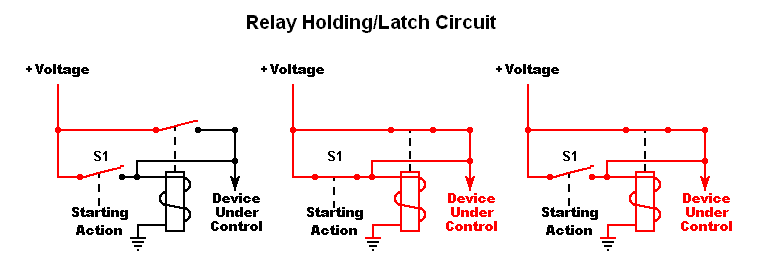
The Holding Circuit (or Latch) has commonly been used to turn on a device with a momentary signal. A brief electrical pulse actuates a holding circuit which keeps power applied after the pulse has ended
The drawing below shows the basic holding/latch circuit. To simplify the diagram, both the relay coil and Device Under Control (load) use the same power source.
First Diagram: Electricity cannot flow to the load (Device Under Control) because of the normally open contacts of switch (S1) and the relay. Second Diagram: closing S1, energizing the relay coil and powering the load (device under control). Third Diagram: Opening off Switch S1, allowing its contacts to open. Normally this would break the circuit and the power will be turned off to the load; however, the closed relay contacts continue supplying current to both the relay coil and the load.
Now we will see how to turn off the load. Our next circuit addresses the problem.
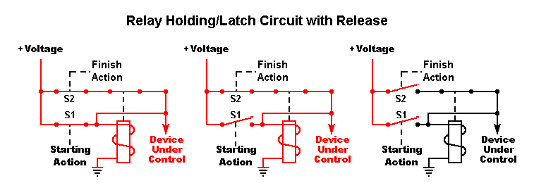
In this circuit we’ve added a normally closed switch (S2). Its purpose is to stop, means powering off the load.
First Diagram: closing S1 and powering the load. Second Diagram: S1 opens, but the latch circuit keeps the load on. Third diagram: When the closed switch S2 opens, de-energizing the relay and stopping the load. Since the relay contacts are now open, closing S2 will not power the load again.
Relay Loop Back Circuit :
Design a relay circuit where each device can turn off the preceding device/load. we have 3 different loads & each have a relay circuit for controlling the power to the load separately one at a time. All loads & Relay have common power source. Each relay have independent input pulse signal to activate the relay & power the load. if load 1 energized then load 2 & load 3 will be in de-energized state. if load 2 energized then load 1 & load 3 will be in de-energized state. if load 3 energized then load 1 & load 2 will be in de-energized state.
The Loop-Back Circuit And finally, the last circuit! Sometimes it’s desirable to have several devices in series. The circuit below shows how each device can turn off the preceding device. This is sometimes called a “loop-back” circuit.
Switches S1, S2 and S3 and the normally open relay contacts prevent all the loads in off state.
When switch S1 closes, energizing the 1st latch, Energizing the load 1.
Load 1 will be in energized state, even though S1 has opened.
When closing S2, energizing the latch of relay-2, turning off the load 1 and energizing the load 2.
Load 2 will be in energized state, even though S2 has opened.
When closing S3, energizing the 3rd latch (relay 3), turning off the load 2 and energizing the load 3.
Load 3 will be in energized state, even though S3 has opened.
When openings S4, releasing the latch and stopping the load 3. Since none of the relays are latched, none of the loads will be energized, even if S4 closes again.
Source : scioly






Really u doing great job god bless u