Inst ToolsInst ToolsInst Tools
  • Courses
  • Automation
    • PLC
    • Control System
    • Safety System
    • Communication
    • Fire & Gas System
  • Instrumentation
    • Design
    • Pressure
    • Temperature
    • Flow
    • Level
    • Vibration
    • Analyzer
    • Control Valve
    • Switch
    • Calibration
    • Erection & Commissioning
  • Interview
    • Instrumentation
    • Electrical
    • Electronics
    • Practical
  • Q&A
    • Instrumentation
    • Control System
    • Electrical
    • Electronics
    • Analog Electronics
    • Digital Electronics
    • Power Electronics
    • Microprocessor
  • Request
Search
  • Books
  • Software
  • Projects
  • Process
  • Tools
  • Basics
  • Formula
  • Power Plant
  • Root Cause Analysis
  • Electrical Basics
  • Animation
  • Standards
  • 4-20 mA Course
  • Siemens PLC Course
Reading: Radar and Ultrasonic Level Transmitter Practical Problems Troubleshooting
Share
Notification Show More
Font ResizerAa
Inst ToolsInst Tools
Font ResizerAa
  • Courses
  • Design
  • PLC
  • Interview
  • Control System
Search
  • Courses
  • Automation
    • PLC
    • Control System
    • Safety System
    • Communication
    • Fire & Gas System
  • Instrumentation
    • Design
    • Pressure
    • Temperature
    • Flow
    • Level
    • Vibration
    • Analyzer
    • Control Valve
    • Switch
    • Calibration
    • Erection & Commissioning
  • Interview
    • Instrumentation
    • Electrical
    • Electronics
    • Practical
  • Q&A
    • Instrumentation
    • Control System
    • Electrical
    • Electronics
    • Analog Electronics
    • Digital Electronics
    • Power Electronics
    • Microprocessor
  • Request
Follow US
All rights reserved. Reproduction in whole or in part without written permission is prohibited.
Inst Tools > Blog > Level Measurement > Radar and Ultrasonic Level Transmitter Practical Problems Troubleshooting

Radar and Ultrasonic Level Transmitter Practical Problems Troubleshooting

In this article, we will learn the radar and ultrasonic level transmitter practical problems and Troubleshooting solutions.

Last updated: July 9, 2024 10:19 am
Editorial Staff
Level Measurement
No Comments
Share
5 Min Read
SHARE

Today we will discuss about troubleshooting steps which we can follow in case we encounter problems in radar level transmitter or ultrasonic level transmitter.

Level Transmitter Problems

Radar and Ultrasonic Level Transmitter Problems Troubleshooting
  1. Check the supply voltage to the level transmitter. If no voltage is present, then check the fuse healthiness in the marshalling cabinet.
  2. If fuse is ok, then check the barrier/isolator condition. If found faulty, then replace it. If found ok, then check all the intermediate connections.
  3. Any connections might be loose. Also check the cable healthiness by checking the resistance of the cable. Replace the cable pair with a spare cable pair if found faulty. 
  4. Replace the transmitter power card if the incoming voltage is present but the transmitter doesn’t power ON.
  5. If level sensor value remains 0% or 100%, do a power reboot of the transmitter. 
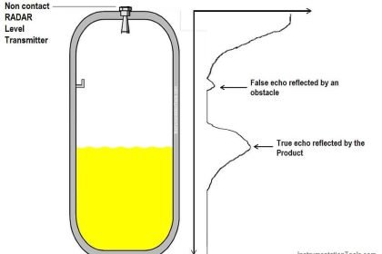
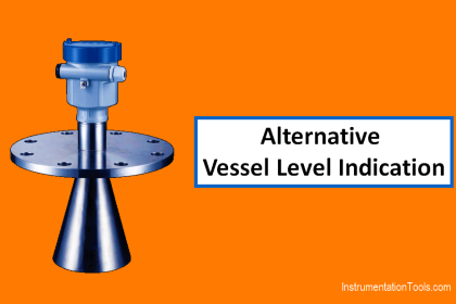
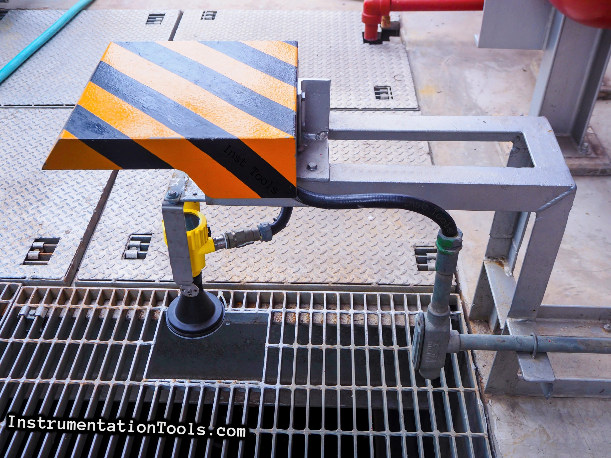
  6. After power reboot, if still value remains 0% or 100%, then in case of non-contact type radar and ultrasonic level transmitter, remove the level transmitter from the tank or vessel. Clean the transmitter’s sensor part. Many times, moisture droplets or vapors get deposited on the sensor and hence we get low or high readings. Clean the sensor with a soft cloth. Also inspect the physical condition of the sensor. In case of radar type level transmitter, check the physical healthiness of the sensor cone.
  7. Check the flange and the path of the waves. Many times, for water service, spider forms web in the path of the radar/ultrasonic waves. So, remove the spider web. Also, sometimes rusting can form bulged structures. This bulged structures also reflect the waves directly and hence we get low or high readings in the level transmitter. So, remove that rusted part. Try to make that portion straight by buffing.
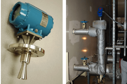
  8. If guided wave radar is used with extended pipe connections, then check whether the valves for extended pipe are open or not.
  9. For guided wave radar level sensor, if power reboot doesn’t work, then first remove the transmitter from the probe part. Clean the tip of the transmitter and the probe tip. Reinstall and check whether the level transmitter works or not.
  10. If still level sensor values are not proper then removing the radar level transmitter’s probe is the step. Remove the probe and clean the probe. Some material might be sticked on the probe. Inspect the probe properly and remove the material.
  11. If above steps do not work then try replacing the respective internal cards.
  12. After installation of the radar transmitter and probe, if still the transmitter is stuck on certain level reading, then again remove the probe. Do steam jetting or hydro jetting on the probe. This will remove the material stuck on the probe’s surface.
  13. Also clean the still pipe used for guided wave radar if present.
  14. If there is value mismatch in the field and the PLC or DCS system, then check both the configured ranges in the field as well as the control system. Confirm the configured ranges with level coordination diagram or any other approved documents available at plant.
  15. If the level transmitter’s value is fluctuating, then physically check whether the level is still in the vicinity of the level transmitter or not. Too much fluctuation in level or air bubbles can also create issue in level measurement. Try changing the installation location of the level transmitter if possible.
  16. If value of level is fluctuating very fast, then try increasing the time constant (damping value) by few seconds. 

Read Next

  • Electrical Ground Loops
  • Purging of Instruments
  • Purged Impulse Lines
  • Impulse Steam Traps
  • Impulse Piping Installation
Don't Miss Our Updates
Be the first to get exclusive content straight to your email.
We promise not to spam you. You can unsubscribe at any time.
Invalid email address
You've successfully subscribed !

Continue Reading

Calibration of Displacer Level Transmitter
Magnetostrictive Level Transmitter Calibration Procedure
Guided-Wave Radar Instruments Diagnostics
Level Indicators Working Principle
DP Transmitter with Two Seals applications
Ultrasonic Level Transmitter Animation
Share This Article
Facebook Whatsapp Whatsapp LinkedIn Copy Link
Share
Leave a Comment

Leave a Reply Cancel reply

Your email address will not be published. Required fields are marked *

Stay Connected

128.3kFollowersLike
69.1kFollowersFollow
210kSubscribersSubscribe
38kFollowersFollow

Categories

Explore More

Differential Pressure (DP) Level transmitter Installed Above Tapping Point
What is a Submersible Pressure Transmitter? Principle, Advantages
Hydrostatic Level Measurement
Float Type Level Indicator Principle
Closed tank DP Level Transmitter with cleaning leg Calibration
Servo Operated Float Level Measurement
Bubbler Level Measurement Animation
Boiler Three Element Controller Philosophy

Keep Learning

level gauge

Basics of Sight Glass Level Gauge

Displacer Level Sensor

What is Displacer Level Sensor ?

Weight-based Level Instruments Principle

Weight-based Level Measurement Principle

Thermal Differential Level Measurement

What is Thermal Differential Level Measurement?

Closed-tank-DP-Level-Transmitter-with-wet-leg-Zero-elevation-Calibration

Closed tank DP Level Transmitter with wet leg Zero elevation Calibration

Closed-Tank-DP-Type-Level-Measurement-with-wet-leg-and-transmitter-installed-below-tapping-point

Level Measurement with Wet leg and Installed Below Tapping Point

Micro-impulse Level Transmitter Principle

Micro-impulse Level Transmitter Principle

Ultrasonic Level Transmitters Installation

Ultrasonic Level Transmitter Principle, Limitations, Calibration and configuration

Learn More

Introduction to PLC

Introduction to PLC – Advantages of PLC

Levels in Industrial Automation

Five Levels in Industrial Automation

Why counter-current heat exchangers are better than co-currents?

Why Counter-current Heat Exchangers are better than Co-current?

Percentage-to-Current-Conversion

Formula to Calculate 4-20ma from Percentage

Temperature Effect on Wet-Leg System

Effect of Temperature & Pressure on Level Measurement

Profibus network

How Profibus Communication Works

Proportional Controller Response Curve

Proportional Controller Principle

Create an Application in HMI using Tia Portal

Create an Application in HMI using Tia Portal

Menu

  • About
  • Privacy Policy
  • Copyright

Quick Links

  • Learn PLC
  • Helping Hand
  • Part Time Job

YouTube Subscribe

Follow US
All rights reserved. Reproduction in whole or in part without written permission is prohibited.
Welcome Back!

Sign in to your account

Username or Email Address
Password

Lost your password?