Inst ToolsInst ToolsInst Tools
  • Courses
  • Automation
    • PLC
    • Control System
    • Safety System
    • Communication
    • Fire & Gas System
  • Instrumentation
    • Design
    • Pressure
    • Temperature
    • Flow
    • Level
    • Vibration
    • Analyzer
    • Control Valve
    • Switch
    • Calibration
    • Erection & Commissioning
  • Interview
    • Instrumentation
    • Electrical
    • Electronics
    • Practical
  • Q&A
    • Instrumentation
    • Control System
    • Electrical
    • Electronics
    • Analog Electronics
    • Digital Electronics
    • Power Electronics
    • Microprocessor
  • Request
Search
  • Books
  • Software
  • Projects
  • Process
  • Tools
  • Basics
  • Formula
  • Power Plant
  • Root Cause Analysis
  • Electrical Basics
  • Animation
  • Standards
  • 4-20 mA Course
  • Siemens PLC Course
Reading: Studio 5000: Programming Three Motors with Fixed Priorities
Share
Notification Show More
Font ResizerAa
Inst ToolsInst Tools
Font ResizerAa
  • Courses
  • Design
  • PLC
  • Interview
  • Control System
Search
  • Courses
  • Automation
    • PLC
    • Control System
    • Safety System
    • Communication
    • Fire & Gas System
  • Instrumentation
    • Design
    • Pressure
    • Temperature
    • Flow
    • Level
    • Vibration
    • Analyzer
    • Control Valve
    • Switch
    • Calibration
    • Erection & Commissioning
  • Interview
    • Instrumentation
    • Electrical
    • Electronics
    • Practical
  • Q&A
    • Instrumentation
    • Control System
    • Electrical
    • Electronics
    • Analog Electronics
    • Digital Electronics
    • Power Electronics
    • Microprocessor
  • Request
Follow US
All rights reserved. Reproduction in whole or in part without written permission is prohibited.
Inst Tools > Blog > PLC Tutorials > Studio 5000: Programming Three Motors with Fixed Priorities

Studio 5000: Programming Three Motors with Fixed Priorities

Learn how to program three motors with fixed priorities in PLC using the functional block diagram language in Studio 5000 software.

Last updated: September 25, 2024 7:45 am
Viral Nagda
PLC Tutorials
No Comments
Share
7 Min Read
SHARE

In PLC programming, there are many cases when we require multiple outputs to work based on priority. We do not want all the outputs to work; only that will work for those who have higher priority. This ensures efficient and equal runtime of all the outputs. In this post, we will write a PLC program on how to switch three motors based on fixed priorities. We will use functional block diagram language using Studio 5000 software.

Contents
Programming Three Motors with Fixed PrioritiesStudio 5000 Programming

Programming Three Motors with Fixed Priorities

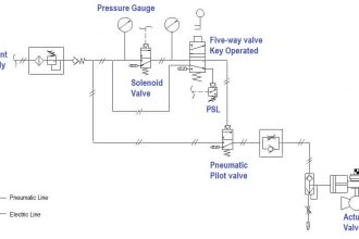
Let us understand the case scenario first. We have a pressure transmitter in a pipeline. This is connected to the discharge line of three pumps. When the pressure is below the on-setpoint, the first pump will turn on after checking for 5 seconds.

If the pressure is still low below this setpoint, then the second pump will turn on after checking for 5 seconds. If the pressure goes above the point after the first pump turns on, then nothing will happen as the pump is maintaining the pressure.

When the pressure is above the off-setpoint, the second pump will turn off after checking for 5 seconds. If the pressure is still above this setpoint, then the first pump will turn off after checking for 5 seconds. If the pressure goes below the setpoint after the second pump turns off, then nothing will happen as the pump is maintaining the pressure.

So, this is basically a pressure-maintaining process as the demand arrives for the pumps. But, all this will run only when the system is running (coming from SCADA). If the system is not running, then no pumps will operate.

First, pumps A and B will operate. Now, an external bit from a SCADA system will come to our PLC which depicts that the set hours of system running has been done. Due to this, we will stop the system first (going from our PLC to SCADA) and pause it for a time till the hours done bit we received is still on. After this bit is off, the system will start again.

Now, pumps B and C will operate. The cycle will again repeat for pumps C and A and will restart again from A and B. Due to this, as the pressure demand varies, the pumps with currently assigned priorities will operate, and the third pump will remain off.

Studio 5000 Programming

Now, let us write the PLC logic. Refer to the below images. We use two sheets in Studio 5000 software, as shown in the two images below.

We have the following input variables – pressure value, pressure on-setpoint, pressure off-setpoint, system running (from SCADA), and set hours done (from SCADA).

We have the following output variables – system pause switchover progress (to SCADA for turning the system running a bit off in its system), pump-1, pump-2, and pump-3.

Studio 5000 Programming Three Motors with Fixed Priorities
PLC configure pumps based on pressure demand

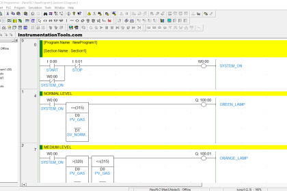
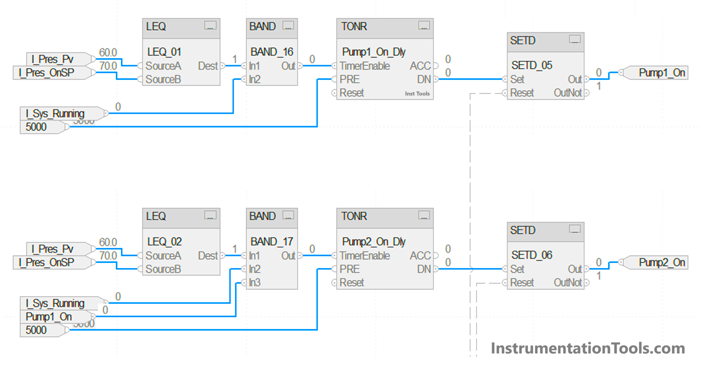
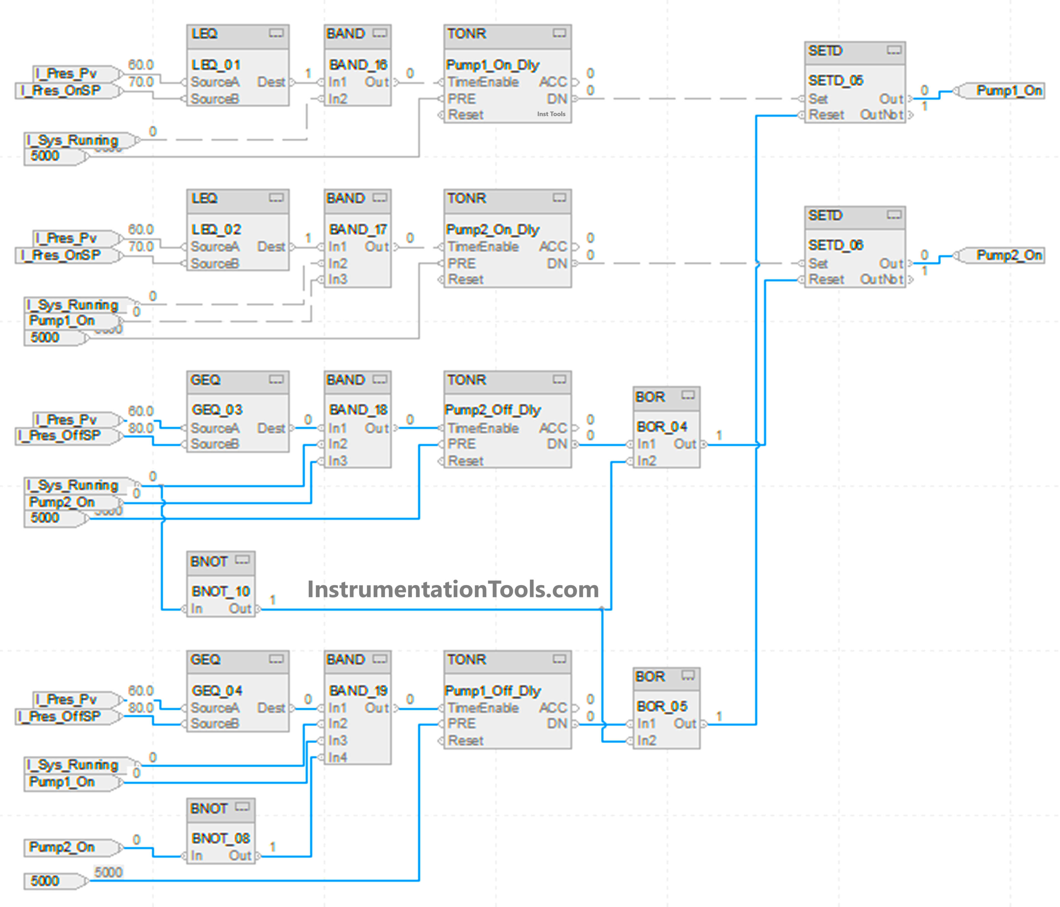
We will take the first sheet, where we will configure pumps based on pressure demand. Refer to the below image, where we turn on the pumps. If the pressure is below on-setpoint and the system is running, we turn on a delay timer for pump-1, which has a setpoint of 5 seconds.

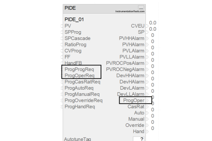
After the timer is done, the bit named pump1_on is set. We use the SETD block here. In this block, there are two inputs – set and reset. If the set bit is high, then the output is set. If the reset bit is high, then the output is reset, on the condition that the set input is not high. It means set input is given priority over reset input.

If the pressure is still below on-setpoint and the system is running and pump-1 is on, we turn on a delay timer for pump-2, which has a setpoint of 5 seconds. After the timer is done, the bit named pump2_on is set. We again use the SETD block here.

Turn off the pumps using PLC

Refer to the below image, where we turn off the pumps. If the pressure is above off-setpoint and the system is running and pump-2 is on, we turn on a delay timer for pump-2, which has a setpoint of 5 seconds. After the timer is done, the bit named pump2_on is reset.

If the pressure is still above off-setpoint and the system is running and pump-2 is off and pump-1 is on, we turn on a delay timer for pump-1, which has a setpoint of 5 seconds. After the timer is done, the bit named pump1_on is reset. If the system is not running, then too we forcefully reset both the bits. So, we use an OR block for resetting the outputs.

Allen Bradley Pumps Logic

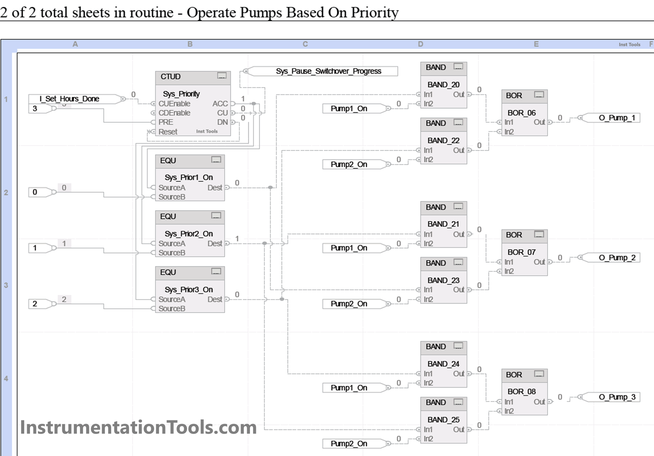
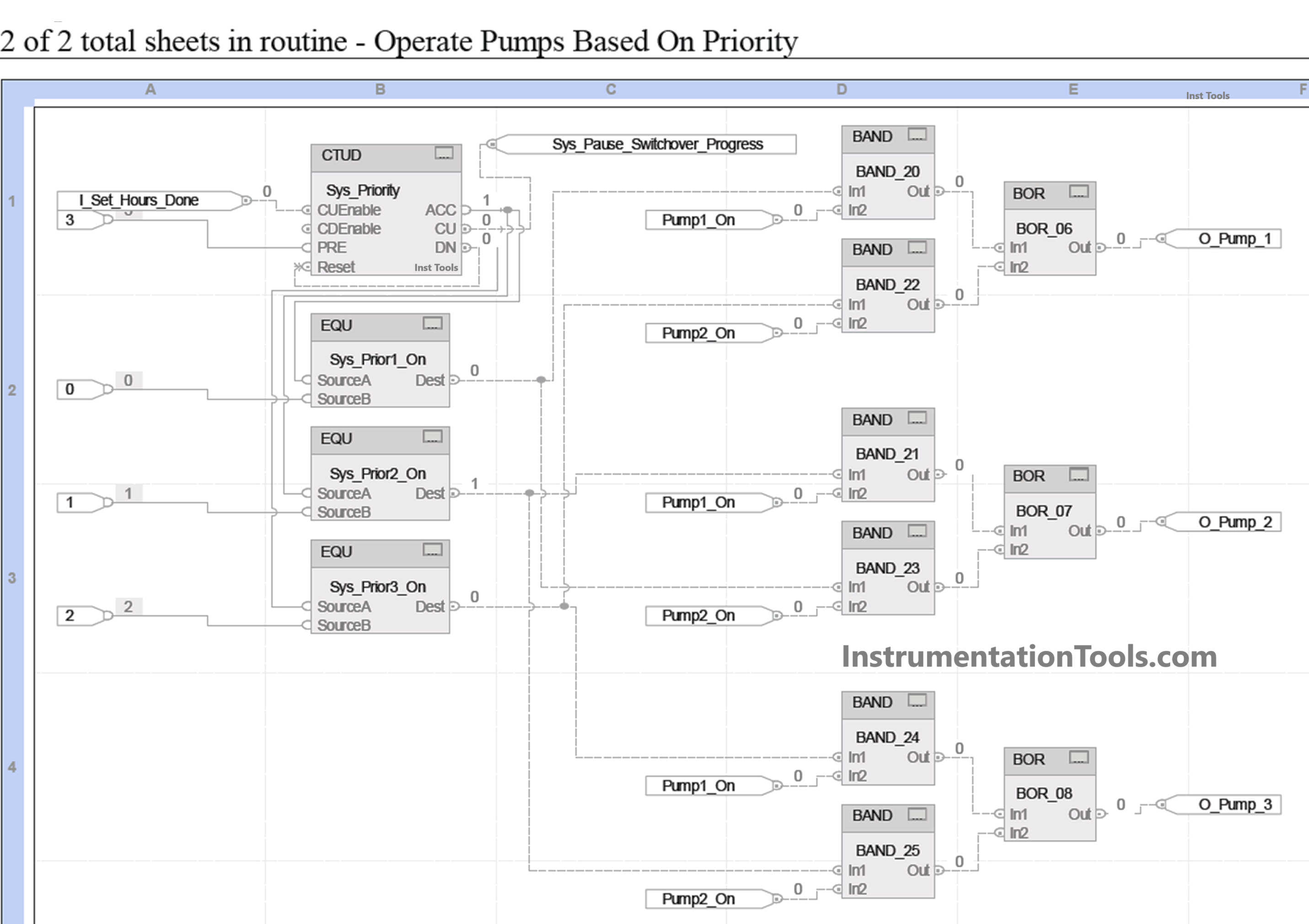
Now, we have to decide where these two bits of pump1_on and pump2_on will be assigned to, meaning which actual pump will operate. We will take the second sheet, where we will operate pumps based on priority. Refer to the below image.

We use a counter for counting system priority based on set hours done from SCADA. Whenever a set operating hours are achieved, the SCADA will give this bit to our PLC and increment the counter. This bit must remain on for some time in SCADA.

Also, when this bit is on, we give in return a bit named system pause switchover progress to SCADA for turning their system off. For the different counter values, we operate the pump according to our design discussed earlier. It will take this counter value and the current pump 1 & 2 condition we wrote earlier. Accordingly, the three pumps will operate.

Rockwell Automation PLC Motor Program

In this way, we saw how to write a PLC program for switching outputs based on fixed priority.

Read Next:

  • PLC Interlock Logic with First Input Priority
  • What is Alarm Prioritization? – Types of Alarms
  • Product Painting with Omron PLC Program
  • PLC Logic for Tanks Filling as per Priority
  • Usage of Cyclic Interrupts TIA Portal (OB 30+)
Don't Miss Our Updates
Be the first to get exclusive content straight to your email.
We promise not to spam you. You can unsubscribe at any time.
Invalid email address
You've successfully subscribed !

Continue Reading

ON Delay Timer using PLC
HMI Screen Design for Hazardous Applications
What is an RTU? – Remote Terminal Unit
PID Controller Output Types – PID_PWM and PID_Output
Basic Concepts of the Safety Relay
How to Download EcoStruxure Machine Expert? Schneider PLC Software
Share This Article
Facebook Whatsapp Whatsapp LinkedIn Copy Link
Share
Leave a Comment

Leave a Reply Cancel reply

Your email address will not be published. Required fields are marked *

Stay Connected

128.3kFollowersLike
69.1kFollowersFollow
210kSubscribersSubscribe
38kFollowersFollow

Categories

Explore More

Types of SCADA System Architecture
Basic Conveyor System for Product Handling in Omron PLC
Applications of SCADA
Vendor Document for Project Systems Architecture
Why Use a Current Loop?
Design a Water Pump PLC Program using CX-Programmer
How to Configure Distributed IO in a PLC Project?
SFC Language in PLC Programming

Keep Learning

Global Data Blocks in PLC

What is a Data Block? Global Data Blocks in PLC

Check Block Consistency Tools

Check Block Consistency Tools in Simatic Manager

Readings Mismatch between Field & Control Room

Readings Mismatch between Field & Control Room ? Why

Schneider PLC Programming Example

Schneider PLC Programming Example for Beginners

D flip flop in PLC

D Flip Flop PLC Ladder Logic

Comparison of Control Loops - Open, Closed, Cascade, Feedforward, Ratio

Comparison of Control Loops – Open, Closed, Cascade, Feedforward, Ratio

Redundant system communication cable

What is Interface Module in Siemens PLC?

PLC based Drink Dispenser System

PLC based Drink Dispenser System

Learn More

vibration probe mounting

Mechanical Vibration Switch Principle

MTech Project Ideas for Electronics and Electrical Engineering

100 MTech Project Ideas for Electronics and Electrical Engineering

ON and OFF a Group of Outputs by One Push button PLC Logic

ON and OFF a Group of Outputs by One Push button PLC Logic

% of Reading vs. % of Full Scale Accuracy

% of Reading vs. % of Full Scale Accuracy

Electrical Maintenance Engineer's Biggest Enemy

Electrical Components Overheating – Causes, Troubles, Prevent

Probe Type Radar Level Transmitter

Contact Type Guided Wave Radar Level Transmitter Working Principle

PLC Ladder Logic Example

PLC Ladder Logic Example

Namur Digital Input Card

What is Namur Digital Input Card?

Menu

  • About
  • Privacy Policy
  • Copyright

Quick Links

  • Learn PLC
  • Helping Hand
  • Part Time Job

YouTube Subscribe

Follow US
All rights reserved. Reproduction in whole or in part without written permission is prohibited.
Welcome Back!

Sign in to your account

Username or Email Address
Password

Lost your password?