Valve and cylinder sizing represents possibly the most important element in the design and specification of any pneumatic system. Carried out correctly, it will ensure that capital and operating costs are minimised, while maximising system performance, reliability and efficiency.
Cylinder Sizing
Cylinder applications can be categorised as either:
- STATIC, i.e. clamping, pressing, etc. or
- DYNAMIC i.e. load moving.
In both cases the principle factors which must be considered when calculating the correct cylinder bore size are:
- Amount of thrust required.
- Available air pressure.
- Efficiency of the cylinder
Cylinder Thrust
Cylinder thrust is a function of:
- Piston diameter
- Applied air pressure
- Frictional resistance (efficiency
Required cylinder thrust is generally derived from a known clamping pressure (static) or the force required to move a particular load (dynamic) and is expressed in units of pounds force (lbf), kilogram force (kgf) or newtons (N).
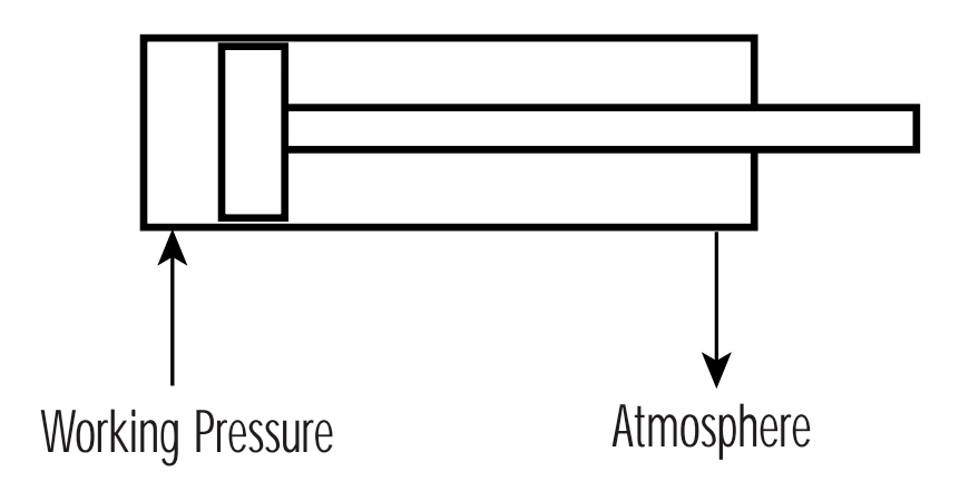
In the case of dynamic applications, consideration must also be given to the decaying pressure on the side of the cylinder piston open to atmosphere.
In order to regulate cylinder speed, the decaying pressure on the side of the cylinder’s piston open to atmosphere, should be approximately 1.5 bar and can be considered to work against the cylinder.
To determine the correct size of cylinder, it is necessary to use the formula:
Thrust = Pressure x Area x Efficiency
Pressure in this instance being the available air pressure, expressed in units of bar, N/m2, lbf/in2 or kgf/cm2, and area being the piston area in units of m2, cm2 or in2. (One bar equals approximately 1 kgf/cm2).
Cylinder efficiency varies between manufacturers, being dependent upon both cylinder construction and the seal technology employed. The general efficiency of cylinders designed with lip seals is considered to be 80% whilst more sophisticated and technologically advanced designs can be as high as 97%.
Example 1:
Determine the size of cylinder (D) required to move a load of 150 kg, given an air pressure of 7.3 bar (7.3 kgf/cm2 ). Assume an efficiency of 90%.
Thrust = Pressure x Area x Efficiency (μ)
therefore, 150 = (7.3 – 1.5) x (π D2 / 4) x 0.9
Transposing this formula then gives:
D2 = (150 x 4) / [(7.3 – 1.5) x p x 0.9] = 36.6 = 6.05 cm
Note : The available pressure of 7.3 bar was reduced by 1.5 bar to allow for decaying pressure on the side of the piston open to atmosphere. The example uses on efficiency of 90%
The result is directly equivalent to the diameter of the cylinder required, measured in centimetres. In practice, however, cylinders with the exact calculated bore size are not usually available. It is therefore necessary to specify a cylinder with the next standard bore size. In this case, a 63mm cylinder would be selected.
Clearly, with a larger bore cylinder, a decrease in working pressure can be tolerated; the difference between available air pressure and required system working pressure being the maximum permissible system pressure drop.
The basic formula used above can also be developed to encompass the extending stroke on a single acting cylinder and the retracting stroke on a double acting device.
For the extending stroke on a single acting cylinder:
FE = P x A x μ – FS
Where:
FE represents the extending cylinder thrust
P = available pressure
A = piston area
μ = efficiency
FS = the spring force at the end of stroke
For the retracting stroke on a double acting cylinder:
FR = π(D2 – d2)/4 x P x μ
Where:
FR represents the cylinder thrust to retract
D = piston diameter
d = piston rod diameter
P = available pressure
μ = efficiency
Note : In this case, no allowance needs to be made for decaying pressure on the side of the piston open to atmosphere since when clamping, the piston will be static and this pressure will be zero.
Example 2:
Determine the size of a cylinder operating at a pressure of 6 bar (600000 N/m2), which would be capable of generating a clamping force of 1600N.
Based on the extending stroke formula:
Thrust = Pressure x Area x Efficiency (μ)
FE = P x πD2/4 x 0.9
therefore, 1600 = 600000 x πD2/4 x 0.9
Transposed to give:
D2 = (4 x 1600)/(600000 x π x 0.9)
D = 0.0614 m
D = 61.4 mm
Again, the next standard size of cylinder would be 63mm.
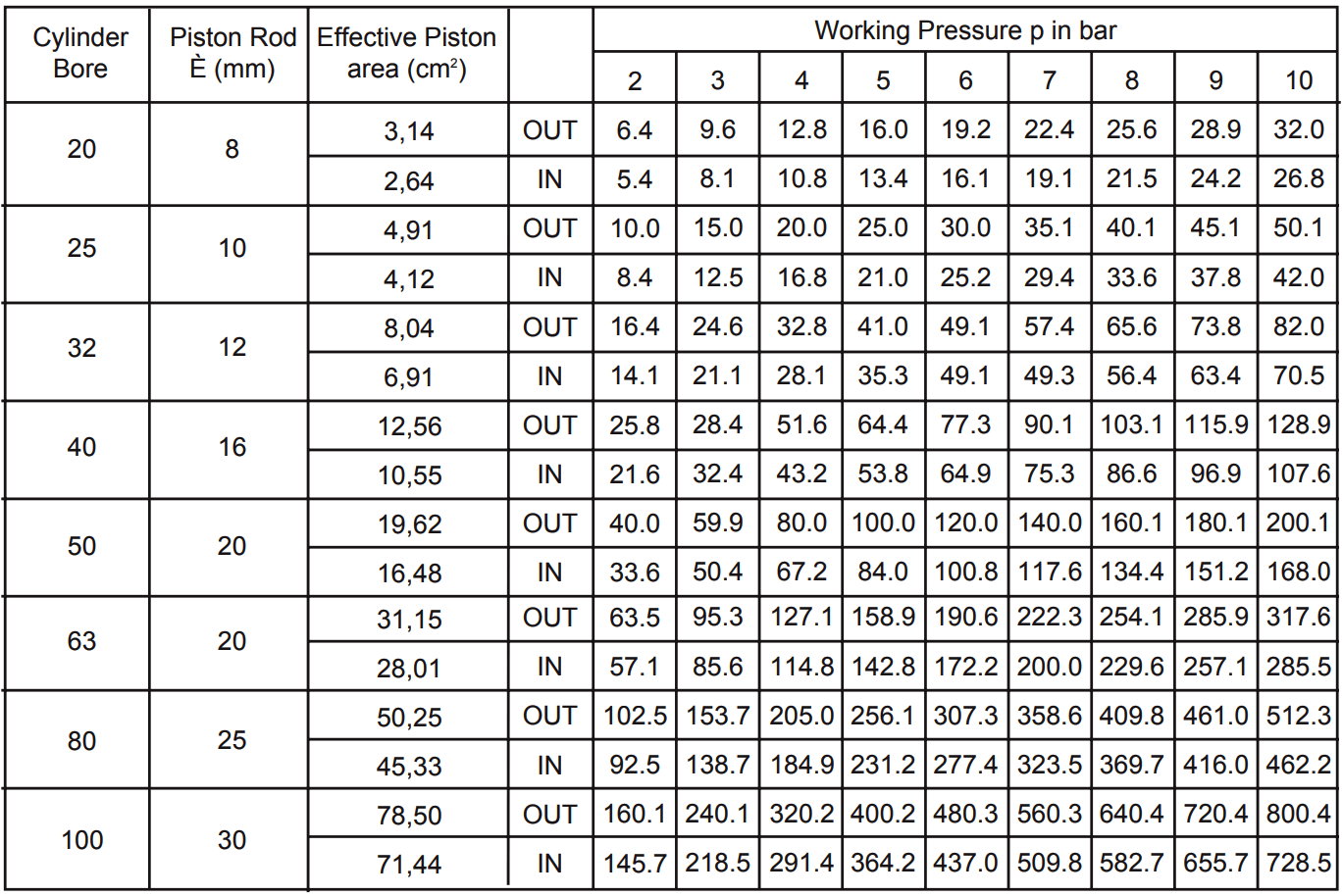
Once these formulae are understood, it is possible to produce a chart on which the theoretical thrust of any given cylinder bore can be shown against any given air pressure. See Figure below.
Note : If cylinder stroke is excessive and working pressure is near to maximum, final cylinder selection should be made in consultation with manufacturers representatives since rod buckling forces may need to be considered.
This chart does not take cylinder efficiency into consideration since this will vary between manufacturers. Values should, therefore, be multiplied by the efficiency factor to obtain usable thrust.
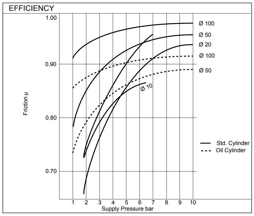
The graph below, Figure 2, allows an efficiency factor (m) to be obtained for various cylinder bore sizes where the supply pressure is known.
Note : The data shown on this graph applies to cylinders produced by SMC Pneumatics. Manufacturers of other cylinders should be consulted to obtain efficiencies for their designs.
Also Read : Pneumatic Valves and Cylinders Sizing – Part 2
Source : smc.eu
