Pneumatic piping employed in plants is used to convey air for two basic reasons:
(1) that of supplying Energy for the operation of instruments and other devices, and
(2) that of transmission of Information between instruments.
Pneumatic Piping
Integrity of the piping system is essential to avoid loss of the pneumatic supply and degradation of the transmitted signals.
Supply air is usually delivered to the control center from external sources at pressures typically between 60 and 150 psi gage (400–1000 kPa). It should be clean, dry, and suitable for the application and environment.
A sufficient flow of supply air should be available to meet the control center requirements for transient as well as steady state conditions. Displacement of oxygen in the control center or control room, resulting from the use of bleed type instruments when gases other than air are used, should be considered.
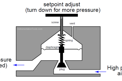
Pressure Reducing Station
A pressure reducing station (sometimes termed as “air set”) reduces and regulates the supply air pressure to a level suitable for the application. The reduced pressure is usually 20 psi gage (140kPa) for systems employing 3–15 psi gage (20–100 kPa) signal ranges and 40 psi gauge (270 kPa) for 6–30 psi gage (40–200 kPa) signal ranges.
Pressure reducing stations are normally located inside the control center but can be external if special access requirements or space limitations exist.
Sizing
The number of air users in the control center establishes the capacity requirements. It is a common practice to determine the total instantaneous air usage by adding together the maximum consumption of each pneumatic device and multiplying by safety or sizing factor of 1.3 to 2.0.
Air filters and pressure regulators are selected from manufacturers’ capacity data based on the total adjusted instantaneous usage and required regulated pressure.
Design
An installation of dual pressure regulators and dual air filters is generally employed. They are arranged in parallel with appropriate valving so that one system can be serviced while the other is in use.
When 3-way valves are used, they should not interrupt the supply to the instruments during a transfer from one leg to the other. Pressure gauges should be provided in each leg to indicate the pressure of the regulated air. A pressure gauge may also be installed to indicate the pressure of the supply air.
A pressure gauge with a blow-out back or disc and a plastic lens is recommended. Low air pressure alarms are often initiated from suitable pressure switches at the pressure reducing station. Adequate clearance is necessary to provide for service and maintenance of the system.
Regulated Air Supply Header
The regulated air is normally piped to a larger diameter plastic or non-ferrous metal pipe section acting as a manifold or header and reservoir from which each air user receives its supply.
The headers are normally installed in a horizontal or vertical plane in the lower part of the control center and have individual shut-off valves at each air supply take-off point. Each shut-off valve should be identified with a non-corrosive metal or plastic tag. It is a good practice to provide up to 15 percent spare valved connections.
The assembly is normally mounted in a rigid manner, sloping at least 1/8 inch per foot away from the supply end, down toward a drain cock. If there is the possibility that failure of the pressure reducing station could result in over pressure damage to the air users, a suitably sized safety relief valve should be installed. The safety relief valve should be sized to pass the rated flow capacity of one regulator failing full open.
The individual air users are connected to the header shut-off valves by tubing. This supply tubing is typically 1/4 inch outside diameter soft copper, plastic, or stainless steel. Some devices with larger air usage may require supply tubing of 3/8 inch or 1/2 inch outside diameter, as suggested by the specifications for that device.
It is a general practice to increase the volume of the air supply header as the number of air users increases. To minimize the pressure drop across the air supply header during large transients in air demand, it is a common practice to use larger diameters and longer sections of pipe.
Interest to add any further points? Share with us through below comments section.
Read Next:
- Junction Box Schedule
- Thermowell Specification
- Temperature Gauges
- Instrument Process Datasheet
- All About Turbine Meters