Inst ToolsInst ToolsInst Tools
  • Ask
  • Courses
  • Videos
  • Q & A
    • Interview
      • Instrumentation
      • Electronics
      • Electrical
      • Practical Questions
    • MCQ
      • Instrumentation MCQ
      • Electrical MCQ
      • Electronics MCQ
      • Control Systems MCQ
      • Analog Electronics MCQ
      • Digital Electronics MCQ
      • Power Electronics MCQ
      • Microprocessor MCQ
      • Multiple Choice Questions
  • EE
    • Electronics
      • Electronics Q & A
      • Electronic Basics
      • Electronic Devices & Circuits
      • Electronics Animation
      • Digital Electronics
    • Electrical
      • Electrical Basics
      • Electrical Q & A
      • Power Electronics
      • Electrical Machines
      • Electrical Animation
      • Power Systems
      • Switchgear & Protection
      • Transmission & Distribution
  • Measure
    • Control Valves
    • Calibration
    • Temperature
    • Pressure
    • Flow
    • Level
    • Analyzers
    • Switches
    • Vibration
    • Solenoid Valve
  • Control
    • PLC Tutorials
    • Control Systems
    • Safety Instrumented System (SIS)
    • Communication
    • Fire & Gas System
  • More
    • Design
    • Tools
    • Animation
    • Basics
    • Formulas
    • Standards
    • TextBooks
    • Common
    • Software
    • Excel Tools
    • Erection & Commissioning
    • Process Fundamentals
    • Videos
    • Books
Search
All rights reserved. Reproduction in whole or in part without written permission is prohibited.
Reading: PLC Structured Text Program for Output Generation via Equations
Share
Notification Show More
Font ResizerAa
Inst ToolsInst Tools
Font ResizerAa
  • Courses
  • PLC Tutorials
  • Control Systems
Search
  • Ask
  • Courses
  • Videos
  • Q & A
    • Interview
    • MCQ
  • EE
    • Electronics
    • Electrical
  • Measure
    • Control Valves
    • Calibration
    • Temperature
    • Pressure
    • Flow
    • Level
    • Analyzers
    • Switches
    • Vibration
    • Solenoid Valve
  • Control
    • PLC Tutorials
    • Control Systems
    • Safety Instrumented System (SIS)
    • Communication
    • Fire & Gas System
  • More
    • Design
    • Tools
    • Animation
    • Basics
    • Formulas
    • Standards
    • TextBooks
    • Common
    • Software
    • Excel Tools
    • Erection & Commissioning
    • Process Fundamentals
    • Videos
    • Books
Follow US
All rights reserved. Reproduction in whole or in part without written permission is prohibited.
Inst Tools > Blog > PLC Tutorials > PLC Structured Text Program for Output Generation via Equations

PLC Structured Text Program for Output Generation via Equations

In this article, we will write a sample PLC program on how to generate output based on equations using structured text language.

Last updated: September 16, 2024 4:50 am
Viral Nagda
PLC Tutorials
No Comments
Share
4 Min Read
SHARE

When you are doing mathematical calculations in a PLC program, you need to understand how to derive proper answers and get the desired result. Accordingly, the logic will help in keeping the calculations and answers intact.

Contents
Output Generation via EquationsPLC Structured Text Program

One of the most preferred languages in PLC programming for writing equations is structured text. This is because the syntax and instruction suits them the best. In this post, we will write a sample program on how to generate output based on equations using structured text language.

Output Generation via Equations

Let us understand the case scenario first. There is a PLC digital output and two PLC inputs – one analog and one digital. The PLC output is controlled through formulae.

The analog input has a range of 0-100%. When the value of that input is more than 30%, a fixed value of 4 is added every 5 seconds.

After addition, when this value becomes more than 20, then the output turns on and the value is subtracted with a fixed value of 4 every 5 seconds. It will subtract till 0 and then, the output turns off.

Again, the cycle continues for addition and subtraction. During this sequence, if the value of the analog input goes less than 30%, then the whole cycle stops. The digital input is an emergency button, which when received, will reset the whole cycle.

PLC Structured Text Program

Now, we will write the logic for the same. Refer to the below image. We take a common timer of 5 seconds for the whole logic.

The timer runs when the value of analog input is more than equal to 30 and the emergency input is healthy. We use the negate done bit of timer for making the timer self reset and run again.
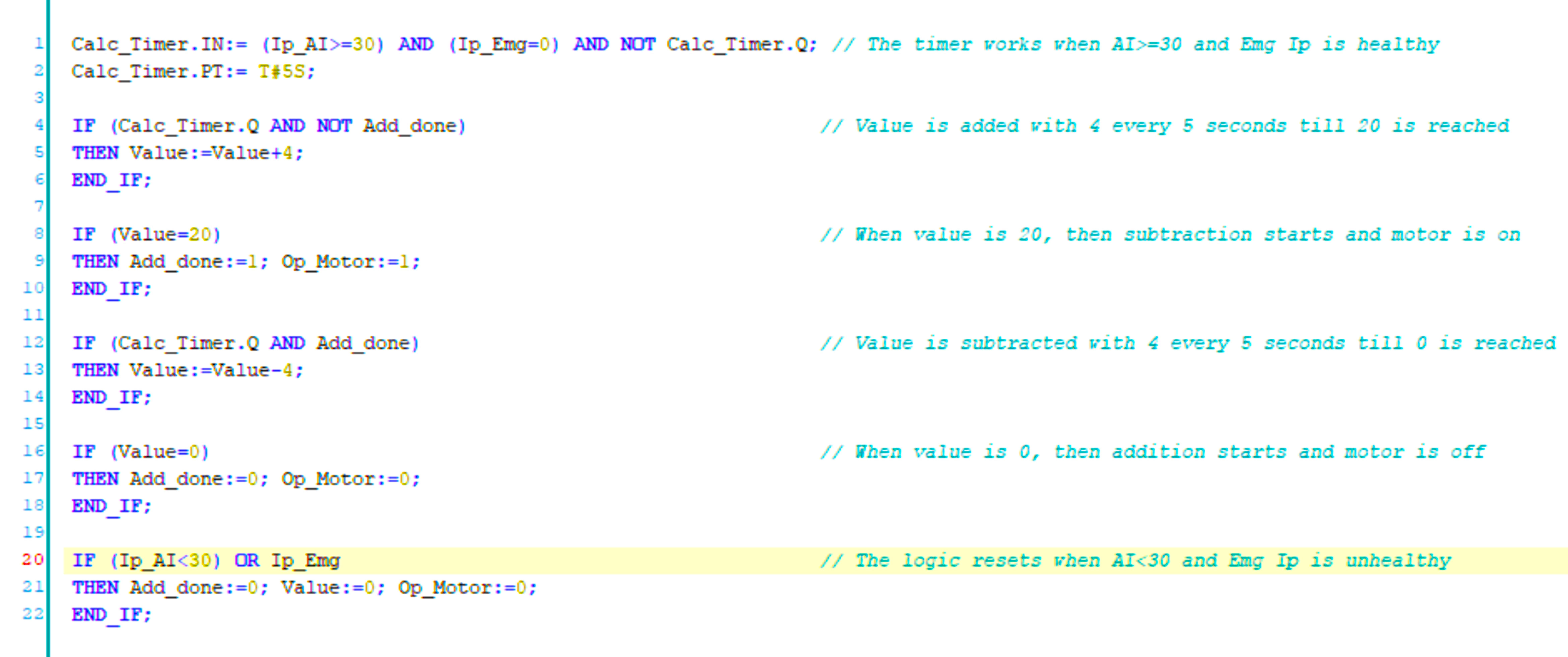
PLC Structured Text Program for Output Generation via Equations

Now, when the timer is done and the value has not reached 20 yet, then the value is added with 4. For checking whether the value of 20 has been reached or not, we use a bit add_done with negate condition.

When the value becomes 20, we set the bit add_done and turn on the motor output, by writing a value of 1 to them.

Now, when the timer is done and the value has not reached 0 yet, then the value is subtracted with 4. For checking whether the value of 0 has been reached or not, we use the bit add_done.

When the value becomes 0, we reset the bit add_done and turn off the motor output, by writing a value of 0 to them. Due to this, the second condition is activated once again and the cycle repeats.

In any instance, when the value of analog input becomes less than 30 or if the emergency is pressed, then all the bits and values are reset and the cycle becomes zero.

We have used if-else statements in the whole program for execution. Due to this, the logic becomes easier to write and understand.

In this way, we saw how to operate a PLC output using equations in structured text language.

Read next:

  • Structured Text for two-tank level application
  • Tanks Draining Control in PLC Programming
  • Functional Block Diagram for Oil and Water Logic
  • Structured Text for Measuring Event Duration
  • PLC FBD Example for Tank Liquid Heating Logic
Don't Miss Our Updates
Be the first to get exclusive content straight to your email.
We promise not to spam you. You can unsubscribe at any time.
Invalid email address
You've successfully subscribed !
VFD Simulator Download – Free Yaskawa V1000 Software
PLC Program for Two Way Switch Logic
How to Create New Project Using Simatic Manager
How a 4-20mA Transmitter Works?
RSLogix 5000 PLC Programming Procedure
Share This Article
Facebook Whatsapp Whatsapp LinkedIn Copy Link
Share
Leave a Comment

Leave a Reply Cancel reply

Your email address will not be published. Required fields are marked *

Stay Connected

128.3kFollowersLike
69.1kFollowersFollow
208kSubscribersSubscribe
38kFollowersFollow

Categories

Recent Comments

  • Guifty Shimica on Top Non-PLC Certification Courses for Automation Professionals
  • Guifty Shimica on Top Non-PLC Certification Courses for Automation Professionals
  • MIHARITSOA Aina Sitraka on Top Non-PLC Certification Courses for Automation Professionals
  • Vaishnavi on Free Instrumentation Course for Trainee Engineers

Related Articles

Functional Block Diagram of XNOR Logic Gate

PLC Functional Block Diagram for Logic Gates

LogixPro Simulator Software

Introducing PLC Programming using LogixPro Simulator Software

PLC Instruction List Example for Level Control of Tank

PLC Instruction List Example for Level Control of Tank

Open Loop and Closed Loop System Questions

Open Loop and Closed Loop System Questions Answers

Example of PID Control Instruction

How to Configure PID in Siemens PLC?

Bit Shift Registers PLC Program

PLC Light Sequence Control using Bit Shift Registers

Network Switch

Network Switch Port Allocation Details

PLC Scan Time

PLC Scan Time

More Articles

Power Electronics Objective Questions

Current Source Inverters Objective Questions

Quiz on Alternators, Motors, and Transformers

200+ Quiz on Alternators, Motors, and Transformers

Discrete control system block diagram

Process Control Instrumentation

Safety Integrity Level (SIL)

Flowmeter Characteristics

Flow Meter Characteristics

Top 100 Microcontrollers Project Ideas

Top 100 Microcontrollers Project Ideas

safety PLC programming

SIS Logic Solver

Manometer Measures Differential Pressure

How Manometer Measures Differential Pressure for Different Fluids?

Follow US
All rights reserved. Reproduction in whole or in part without written permission is prohibited.
Welcome Back!

Sign in to your account

Username or Email Address
Password

Lost your password?