Inst ToolsInst ToolsInst Tools
  • Courses
  • Automation
    • PLC
    • Control System
    • Safety System
    • Communication
    • Fire & Gas System
  • Instrumentation
    • Design
    • Pressure
    • Temperature
    • Flow
    • Level
    • Vibration
    • Analyzer
    • Control Valve
    • Switch
    • Calibration
    • Erection & Commissioning
  • Interview
    • Instrumentation
    • Electrical
    • Electronics
    • Practical
  • Q&A
    • Instrumentation
    • Control System
    • Electrical
    • Electronics
    • Analog Electronics
    • Digital Electronics
    • Power Electronics
    • Microprocessor
  • Request
Search
  • Books
  • Software
  • Projects
  • Process
  • Tools
  • Basics
  • Formula
  • Power Plant
  • Root Cause Analysis
  • Electrical Basics
  • Animation
  • Standards
  • 4-20 mA Course
  • Siemens PLC Course
Reading: PLC Sequence Programming Ladder Logic
Share
Font ResizerAa
Inst ToolsInst Tools
Font ResizerAa
  • Courses
  • Design
  • PLC
  • Interview
  • Control System
Search
  • Courses
  • Automation
    • PLC
    • Control System
    • Safety System
    • Communication
    • Fire & Gas System
  • Instrumentation
    • Design
    • Pressure
    • Temperature
    • Flow
    • Level
    • Vibration
    • Analyzer
    • Control Valve
    • Switch
    • Calibration
    • Erection & Commissioning
  • Interview
    • Instrumentation
    • Electrical
    • Electronics
    • Practical
  • Q&A
    • Instrumentation
    • Control System
    • Electrical
    • Electronics
    • Analog Electronics
    • Digital Electronics
    • Power Electronics
    • Microprocessor
  • Request
Follow US
All rights reserved. Reproduction in whole or in part without written permission is prohibited.
Inst Tools > Blog > PLC Tutorials > PLC Sequence Programming Ladder Logic

PLC Sequence Programming Ladder Logic

Write PLC program for Flare application using ladder diagram language using PLC Sequence Programming. Flare Control Valve application uisng PLC Logic.

Last updated: November 3, 2023 3:12 pm
Editorial Staff
PLC Tutorials
1 Comment
Share
6 Min Read
SHARE

This is a PLC Program for sequence control application. Learn PLC programming with interesting examples.

Contents
PLC Sequence ProgrammingProblem DiagramProblem SolutionList of Inputs and OutputsPLC Program for Sequence ControlProgram Description

PLC Sequence Programming

Problem Description

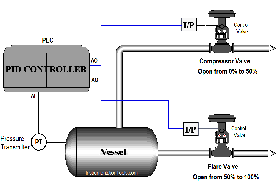
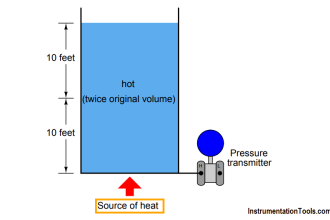
In flare application, fluid or gas is processed in a vessel. If the pressure is low in vessel, both the valves should be closed.

Compressor valve continues to open until PID controller output reaches 50%. Flare valve will start if the pressure in the vessel still increases.

Write PLC program for this flare application using ladder diagram language.
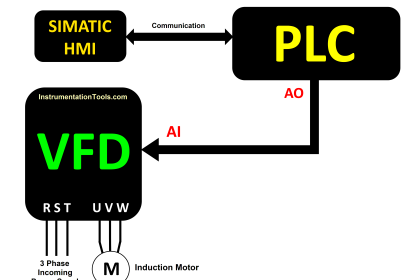
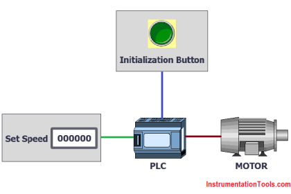
Problem Diagram

PLC Sequence Programming Ladder Logic

Problem Solution

For this application, we will use sequence control concept. Here we are discussing about flare control example.

Two control valves are used for controlling, one is for compressor and other is for flare.

Pressure transmitter is used for pressure control in a vessel.

We use an PID controller in PLC for controlling of two valves as per requirements.

If the pressure is low, the PID controller output is 0% output and both valves are closed and it will allow pressure to build up in the vessel. When pressure increases, the control valve allow product to exit and compressor valve continues to open until controller output reaches 50%.

If the pressure still increases flare valve starts to open to evacuate the gas and burn it. When controller output is 100% both the outputs are fully open.

PLC uses SPLIT programming so you can connect  two control valves with separate analog output. Hence you can calculate output range in PLC.

List of Inputs and Outputs

Inputs List

  • PID enable :- M61.0
  • Manual enable :- M61.1
  • PID reset :- M61.2
  • Analog input from PT :- IW64

Outputs List

  • Compressor control valve analog output :- QW96
  • Flare control valve analog output :- QW98

M memory

  • Set pressure :- MD500
  • Actual pressure :- MD704
  • PID output (%) : -MD758
  • PID state word :- MW770
  • PID error word :- MD778
  • Calculated output for compressor valve :- MD790
  • Calculated output for flare valve :- MD204
  • Scaling word :- MD798
  • PID enable input :- M61.0
  • PID manual mode enable input :- M61.1
  • PID controller reset :- M61.2
  • PID high limit alarm :- M766.0
  • PID low limit alarm :- M766.1
  • PID input warning :- M766.2

PLC Program for Sequence Control

Two Control Valves PLC Logic

Two Control Valves PLC Ladder Diagram

PLC Split Range Control Logic

PLC Sequence Logic PLC Sequence Control PLC Compressor Valve PLC Flare Valve

Program Description

For this application we used S7-1200 PLC and TIA portal software for programming.

Network 1:

In network we configured standard parameters for PID function.

  • “Drive PID”.sRet.r_Ctrl_Gain:- saved proportional gain or P gain for PID (1.0).
  • “Drive PID”.sRet.r_Ctrl_Ti:-Saved integral time or I gain for PID (20s).

Network 2:

“Drive PID”.sRet.r_Ctrl_Td:-Saved derivative time or D gain for PID (0s).

Network 3:

Here we have taken temperature PID max output limit and minimum output limit. We have considered here max limit for PID output 100 and minimum limit is 0.

Network 4:

Sampling time of the PID_Compact instruction r_Cycle is determined automatically and usually equivalent to the cycle time of the calling OB. Consider 0.1s for this application.

Network 5:

When PID enable (M61.0) is pressed PID block will be executed. As per SET point (MD500) it will generate output (0-27648) and according to actual pressure transmitter will give feedback (IW96) to PID.Manual enable (M61.1) is for manual operation and PID reset (M61.2) is for resetting the PID.

Network 6:

Activate Mode after CPU restart If sb_RunModeByStartup = FALSE, the controller will remain inactive after a CPU startup.
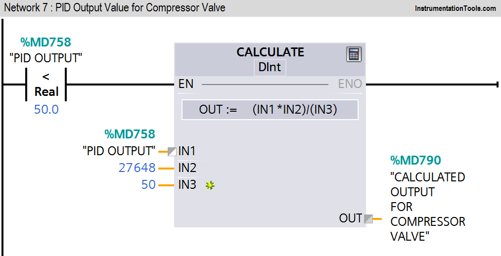
Network 7:

Here we calculated the PID output range for the compressor valve. It will continue to open until PID output reaches 50%.
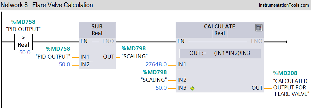
Network 8:

Here we calculated the PID output range for the flare control valve. It will start to open when control output reaches 50%. Hence when controller output reaches 50%, flare valve will start to open and it will be fully open when controller output is 100%.

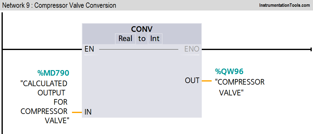
Conversion of calculated output for compressor control valve.
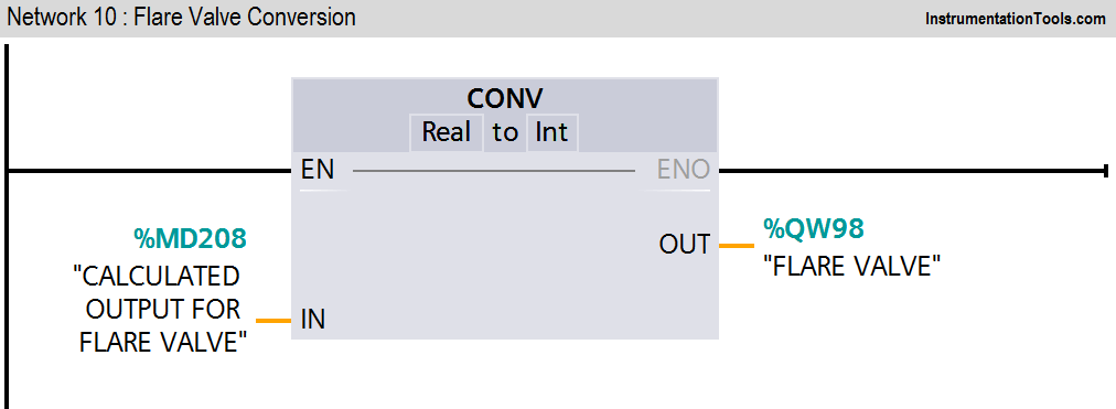
Network 9:

Conversion of calculated output for flare control valve.

Note :- Above application may be different from actual application. We can also make this application by using ready-made PID control and current to pressure converters. This example is only for explanation purpose only. We can implement this logic in other PLC also. This is the simple sequence control application used in industry, we can use this concept in other examples also.

All parameters and graphical representations considered in this example are for explanation purpose only, parameters or representation may be different in actual applications. Also all interlocks are not considered in the application.

Author: Bhavesh

If you liked this article, then please subscribe to our YouTube Channel for PLC and SCADA video tutorials.

You can also follow us on Facebook and Twitter to receive daily updates.

Read Next:

  • Web-based SCADA Software
  • PLC Program Examples
  • Relay Noise in PLC Systems
  • Water Level Control PLC Logic
  • PLC Comparator Logic
Don't Miss Our Updates
Be the first to get exclusive content straight to your email.
We promise not to spam you. You can unsubscribe at any time.
Invalid email address
You've successfully subscribed !

Continue Reading

Open Source PLC and SCADA Software
#20 PLC Best Practices – Identify Critical Alerts
Troubleshoot Allen Bradley PLC Logic
PLC Programming for Baking with Auto and Manual Modes
Studio 5000: Define Program or Operator Control in Functional Block Diagram
Waste-Burning System OMRON PLC Program Example
Share This Article
Facebook Whatsapp Whatsapp LinkedIn Copy Link
Share
1 Comment
  • Parth Tiwari says:
    August 31, 2021 at 7:46 pm

    May I get the book of plc examples. Of start delta motor, pid logic etc. For better understanding.

    Reply

Leave a Reply Cancel reply

Your email address will not be published. Required fields are marked *

Stay Connected

128.3kFollowersLike
69.1kFollowersFollow
210kSubscribersSubscribe
38kFollowersFollow

Categories

Explore More

Tia Portal – Optimized and Standard Data Block Access
Example PLC Program
PLC Techniques for I/O Mapping
PLC Timer Practice Exercise: Coffee Machine Programming
Comparison of Control Loops – Open, Closed, Cascade, Feedforward, Ratio
Create an Application in HMI using Tia Portal
PLC Program to Control a Water Pump
Communicating Delta PLC Software to Simulator

Keep Learning

How to Troubleshoot a PLC System

How to Troubleshoot a PLC System?

Statement List (STL) to Find Highest Value in the Data Block

Statement List (STL) to Find Highest Value

What is Loop Checking

What is Loop Checking?

Schneider Electric Modicon M340 PAC

PLC vs PAC – Understanding the Key Differences and Similarities

Siemens CPU MP Port

Siemens S7-300 CPU Suffix Explanation

Distributed Control System Interview Questions

Why 24 Volts DC Power Supply

Why 24 Volts DC Power Supply is used? – Industrial Automation Systems

PLC Program for Valves

PLC Pump Permissive Interlocks

Learn More

Non-variable reducing valves

What is Reducing Valve ?

L2F insertion-style flowmeter

Optical Flow Meter Principle

3 Wire RTD Connections

RTD Sensor Connections

Power Electronics Objective Questions

Types of Diodes Quiz

What is Gas Chromatography

What is Gas Chromatography?

Power Electronics Objective Questions

Three Phase Converter Multiple Choice Questions

Smart DP transmitter Formula

Smart DP Transmitter Flow Meter Calculations

Wattmeter Principle

Wattmeter

Menu

  • About
  • Privacy Policy
  • Copyright

Quick Links

  • Learn PLC
  • Helping Hand
  • Part Time Job

YouTube Subscribe

Follow US
All rights reserved. Reproduction in whole or in part without written permission is prohibited.
Welcome Back!

Sign in to your account

Username or Email Address
Password

Lost your password?