Design a program for PLC pump control such that the pump must be turned ON for 10 seconds and turned OFF for 20 seconds.
Note: The plc programming example is prepared for the engineers who are interested in learning the ladder logic with basics.
PLC Pump Control
Problem Statement:
Design a PLC ladder logic for the following application.
We are using one toggle switch to control the pump.
Turn ON the pump for 10 seconds and then turn OFF the pump for 20 seconds and repeat this cycle.
Expert PLC Training
Our PLC training videos explain the basic concepts and PLC programming for beginners with detailed explanations.

Inputs
The required input is listed below.
Start button: I0.0
Outputs
The required output is listed below.
Pump: Q0.0
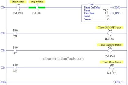
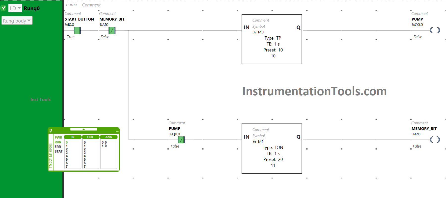
Pump Run for 10 seconds & OFF for 20 seconds Logic
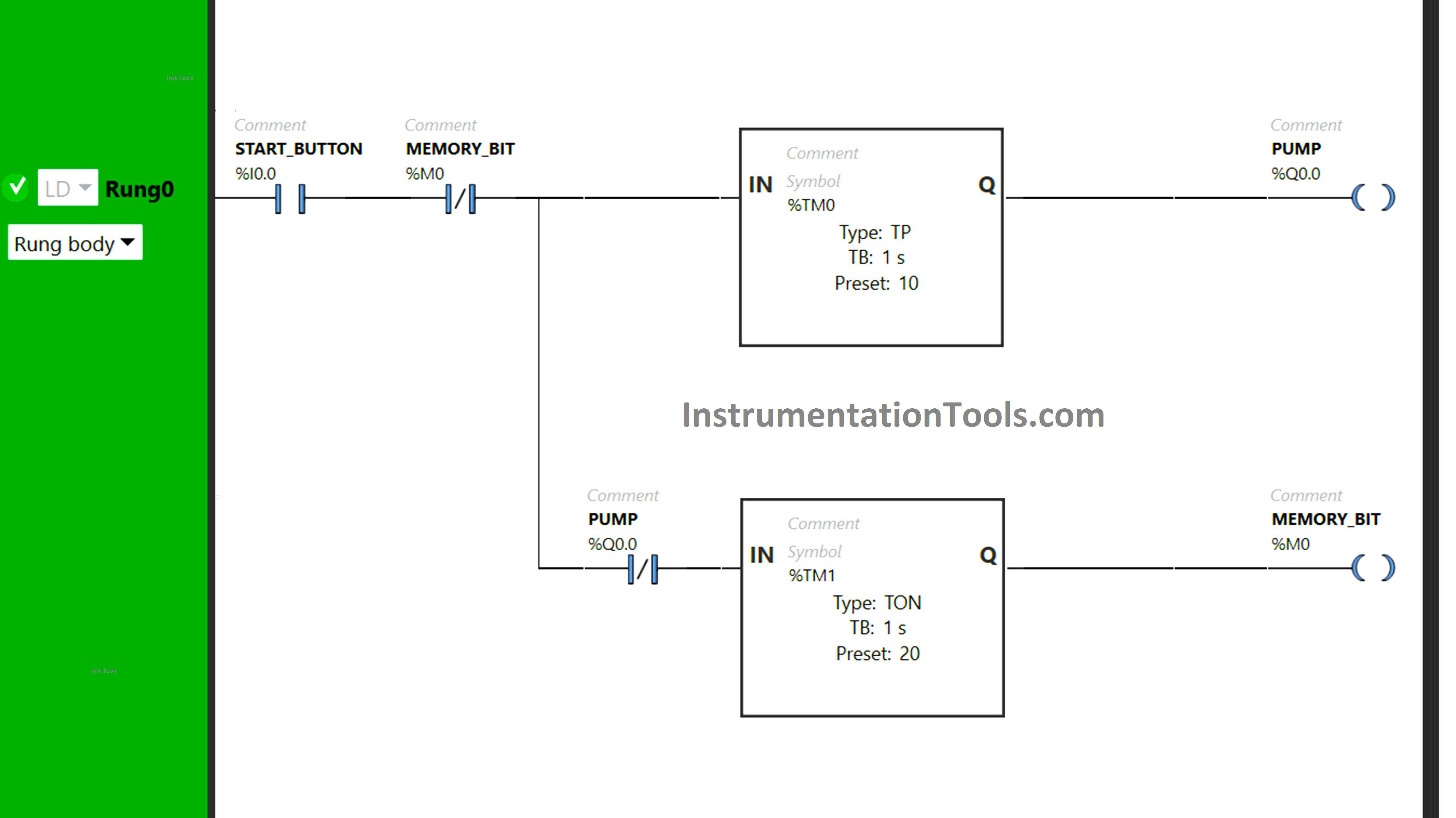
Program Description
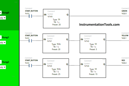
We used Normally Open Contact for the Start button.
Two Timer Function Blocks Type TON and TP are used for the Pump and memory bit.
Timer Function Block type TP is used to keep the Pump ON for 10 seconds.
Timer Function Block type TON is used for the Memory bit to turn it ON after a delay of 20 seconds.
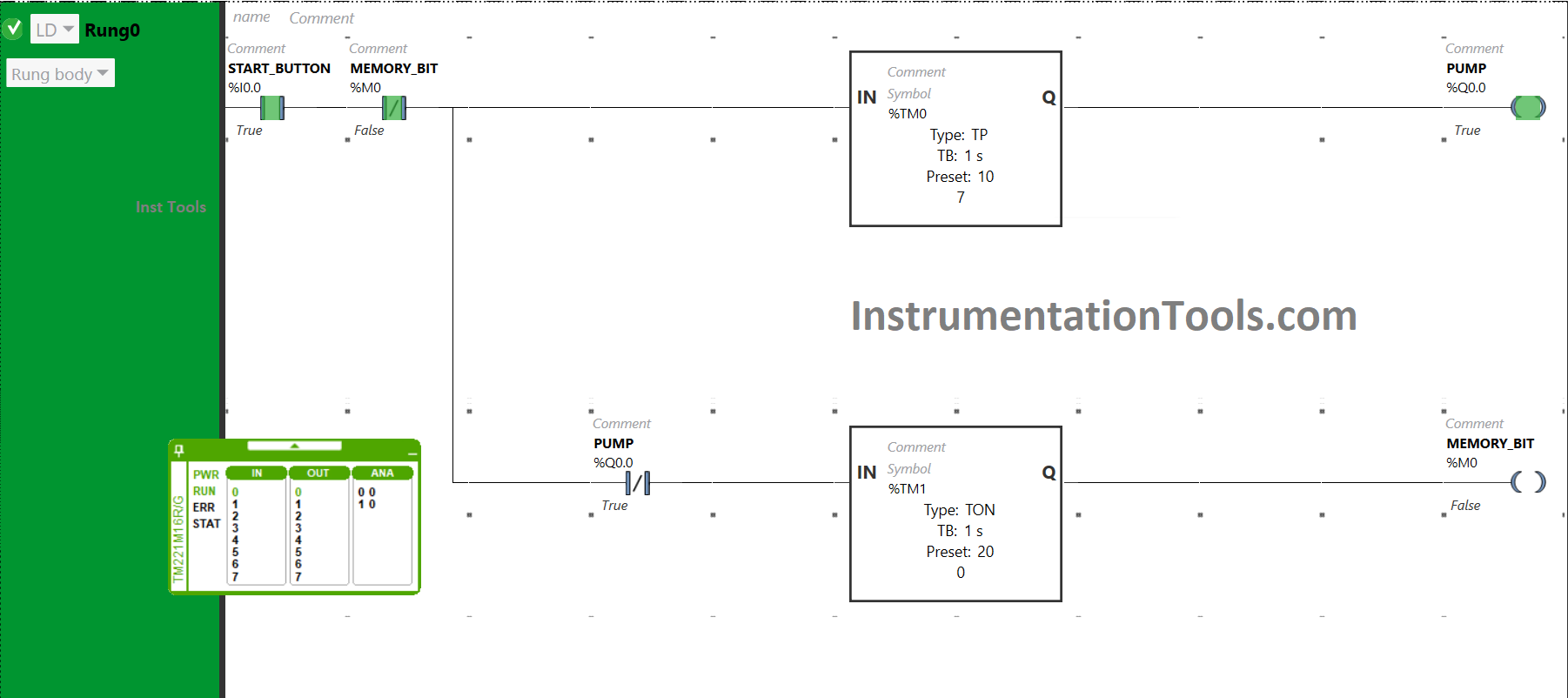
PLC Program Result
When the Start button is turned ON, the signal will flow also through the Normally Closed Contact that is used for memory bit as it is false state. Timer functional block type TP (TM0) will allow the signal to flow for a period of 10 seconds only.
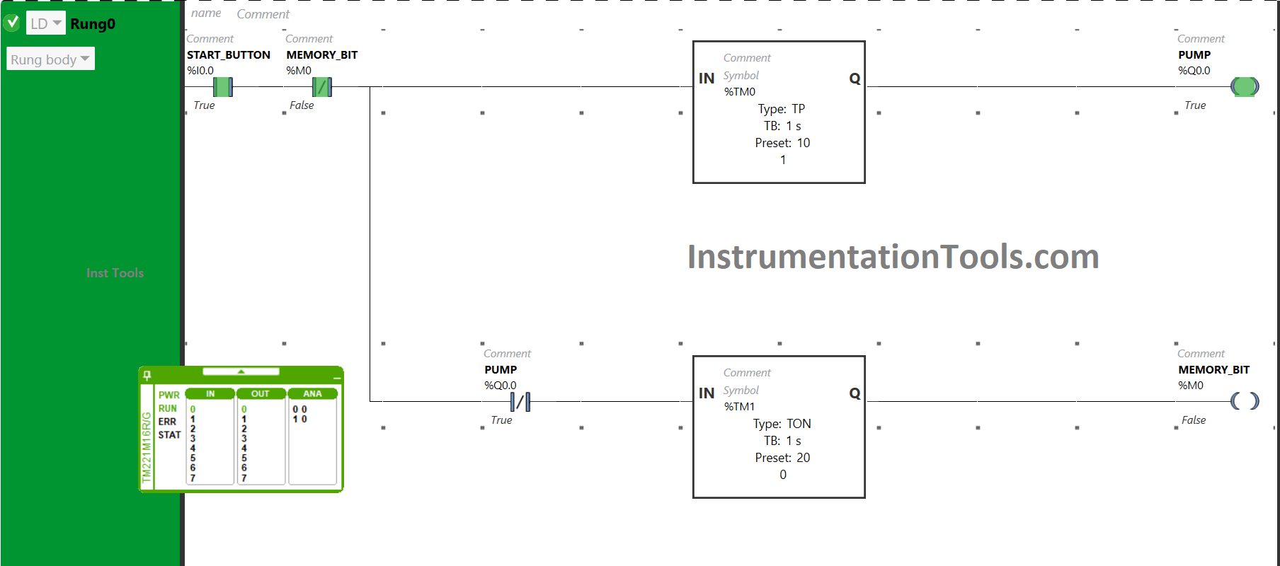
As a result, the pump will be turned ON. After 10 seconds, the signal will not flow because of the Timer functional block type TP (TM0). And pump will turn OFF after being ON for 10 seconds.
When the Start button is turned ON and when the pump gets turned OFF after being ON for 10 seconds, the signal will flow through the Normally Closed contact used for PUMP. There will be a delay of 20 seconds and after that memory bit gets true. In those 20 seconds, the motor will remain OFF.
After a delay of 20 seconds, the coil used for the memory bit becomes true, and the Normally Closed Contact used for the Memory Bit will also become true. The Normally Closed Contact in its true state will break the circuit.
As a result, the coil used for the coil memory bit becomes false which in turn makes the Normally Closed Contact used for the memory bit false. And the signal will again pass to the pump and it will be turned ON for 10 seconds. After that, it will remain OFF for 20 seconds and then it will repeat the process again and again.
If you liked this article, please subscribe to our YouTube Channel for PLC and SCADA video tutorials.
You can also follow us on Facebook and Twitter to receive daily updates.
Read Next:
- PLC Programming Example with Motor
- PLC Push Button to Turn ON or OFF Output
- PLC Code to Start & Stop Motor and Pump
- Electrical Ladder Diagram Control with Timers
- Controlling the PLC Output using Push Buttons