Inst ToolsInst ToolsInst Tools
  • Courses
  • Automation
    • PLC
    • Control System
    • Safety System
    • Communication
    • Fire & Gas System
  • Instrumentation
    • Design
    • Pressure
    • Temperature
    • Flow
    • Level
    • Vibration
    • Analyzer
    • Control Valve
    • Switch
    • Calibration
    • Erection & Commissioning
  • Interview
    • Instrumentation
    • Electrical
    • Electronics
    • Practical
  • Q&A
    • Instrumentation
    • Control System
    • Electrical
    • Electronics
    • Analog Electronics
    • Digital Electronics
    • Power Electronics
    • Microprocessor
  • Request
Search
  • Books
  • Software
  • Projects
  • Process
  • Tools
  • Basics
  • Formula
  • Power Plant
  • Root Cause Analysis
  • Electrical Basics
  • Animation
  • Standards
  • 4-20 mA Course
  • Siemens PLC Course
Reading: 3 to 8 Line Decoder PLC Ladder Diagram
Share
Notification Show More
Font ResizerAa
Inst ToolsInst Tools
Font ResizerAa
  • Courses
  • Design
  • PLC
  • Interview
  • Control System
Search
  • Courses
  • Automation
    • PLC
    • Control System
    • Safety System
    • Communication
    • Fire & Gas System
  • Instrumentation
    • Design
    • Pressure
    • Temperature
    • Flow
    • Level
    • Vibration
    • Analyzer
    • Control Valve
    • Switch
    • Calibration
    • Erection & Commissioning
  • Interview
    • Instrumentation
    • Electrical
    • Electronics
    • Practical
  • Q&A
    • Instrumentation
    • Control System
    • Electrical
    • Electronics
    • Analog Electronics
    • Digital Electronics
    • Power Electronics
    • Microprocessor
  • Request
Follow US
All rights reserved. Reproduction in whole or in part without written permission is prohibited.
Inst Tools > Blog > PLC Tutorials > 3 to 8 Line Decoder PLC Ladder Diagram

3 to 8 Line Decoder PLC Ladder Diagram

Implement 3 to 8 line decoder in PLC using ladder diagram programming language. Learn the PLC tutorials with examples.

Last updated: November 3, 2023 1:43 pm
Editorial Staff
PLC Tutorials
No Comments
Share
4 Min Read
SHARE

Implement 3 to 8 line decoder in PLC using ladder diagram programming language.

Contents
3 to 8 Line DecoderProblem SolutionList of inputs/outputsPLC Program to implement 3 to 8 line decoderProgram DescriptionResult

3 to 8 Line Decoder

3 to 8 Line Decoder Circuit Diagram

Problem Solution

For this problem, we will use S7-1200 PLC and TIA portal software for programming.

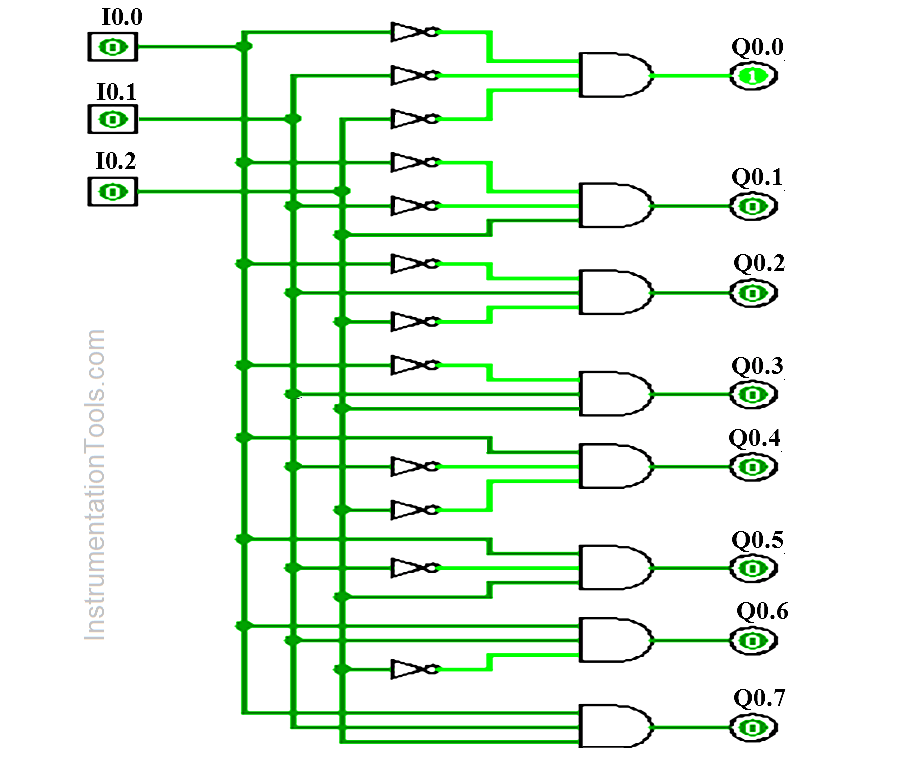
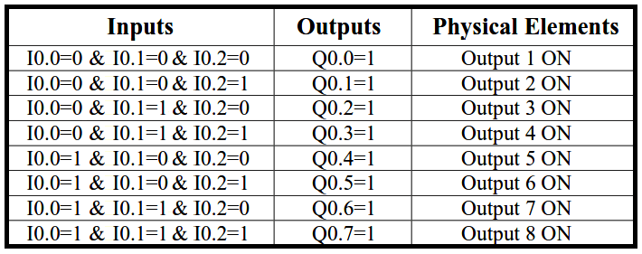
This decoder has three inputs and 8 outputs and these inputs determine which output will be ON.

Here three inputs were used (Input 1-I0.0, Input 2-I0.1, and Input 3-I0.2), and 8 outputs were used (Output 1 to 7, Q0.0 to Q0.7).

If all inputs are OFF, output 1 (Q0.0) will be ON and others are not.

List of inputs/outputs

List of inputs

  • Input 1:- I0.0
  • Input 2 :- I0.1
  • Input 3 :- I1.0

List of outputs

  • Output1 :- Q0.0
  • Output 2 :- Q0.1
  • Output 3 :- Q0.2
  • Output 4 :- Q0.3
  • Output 5 :- Q0.4
  • Output 6 :- Q0.5
  • Output 7 :- Q0.6
  • Output 8 :- Q0.7

PLC Program to implement 3 to 8 line decoder

PLC Program for Decoder Logic
Decoder PLC
3 to 8 line decoder
Decoder Ladder Logic
PLC Decoder Application
PLC Decoder Example
PLC Logic for Decoder
PLC Decoder Program

Program Description

For this application, we used S7-1200 PLC and TIA portal software for programming.
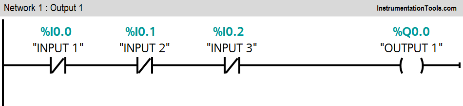
Network 1:

If all inputs are OFF (I0.0=0, I0.1=0 and I0.2=0), Output 1 (Q0.0) will be ON.
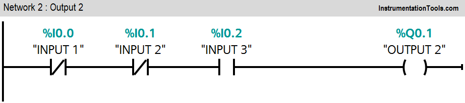
Network 2:

If input 1 (I0.0) and input 2 (I0.1) are OFF and input 3 (I0.2) is ON, Output 2 (Q0.1) will be ON.
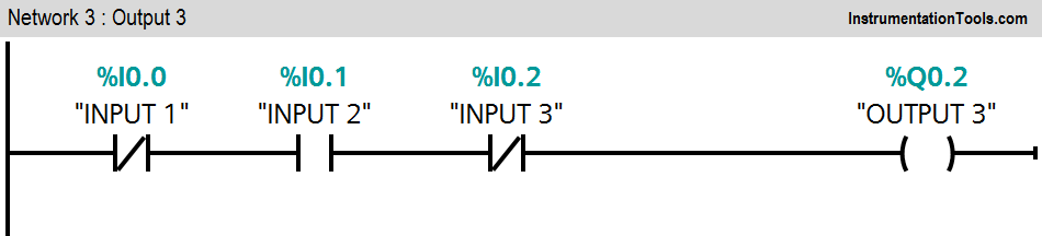
Network 3:

If input 1 (I0.0) and input 3 (I0.2) are OFF and input 2 (I0.1) is ON, Output 3 (Q0.2) will be ON.
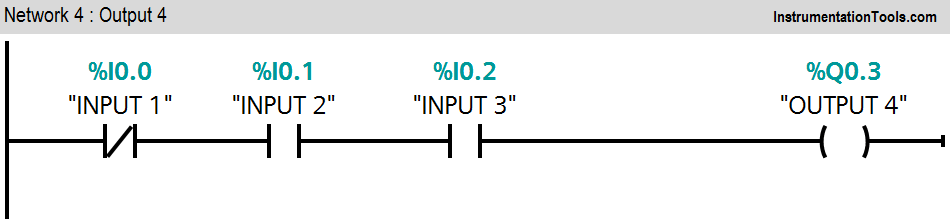
Network 4:

If input 2 (I0.1) and input 3 (I0.2) are ON and input 1 (I0.0) is OFF, Output 4 (Q0.3) will be ON.
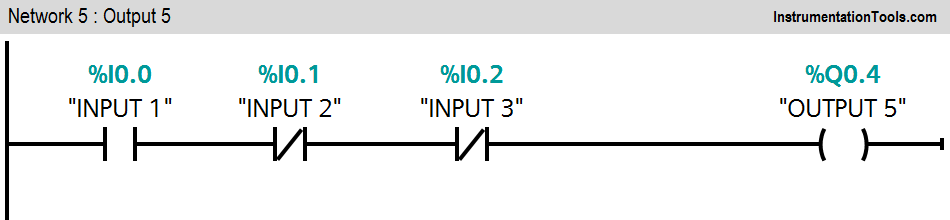
Network 5:

If input 2 (I0.1) and input 3 (I0.2) are OFF and input 1 (I0.0) is ON, Output 5 (Q0.4) will be ON.
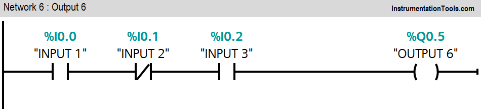
Network 6:

If input 1 (I0.0) and input 3 (I0.2) are ON and input 2 (I0.1) is OFF, Output 6 (Q0.5) will be ON.
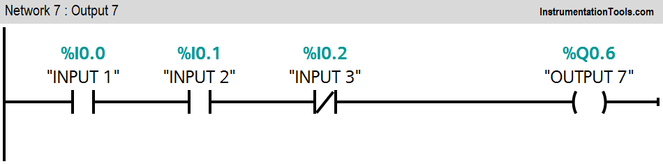
Network 7:

If input 1 (I0.0) and input 2 (I0.1) are ON and input 3 (I0.2) is OFF, Output 7 (Q0.6) will be ON.
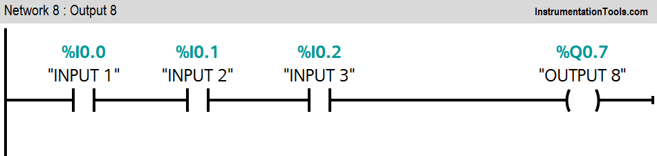
Network 8:

If input 1 (I0.0) and input 2 (I0.1) and input 3 (I0.2) are ON, Output 8 (Q0.7) will be ON.

Note :- Above application may be different from actual application. This example is only for explanation purpose only. We can implement this logic in other PLC also. This is the simple concept of 3 to 8 line decoder, we can use this concept in other examples also.

All parameters considered in example are for explanation purpose only, parameters may be different in actual applications. Also all interlocks are not considered in the application.

Result

3 to 8 Line Decoder

Author: Bhavesh

If you liked this article, then please subscribe to our YouTube Channel for PLC and SCADA video tutorials.

You can also follow us on Facebook and Twitter to receive daily updates.

Read Next:

  • PLC 3 Phase Asynchronous Motor Control
  • Energize & De-energize the Outputs using PLC
  • PLC Level Control of Parallel Tanks
  • GE PLC Ladder logic program download
  • Allen Bradley PLC Subroutines
Don't Miss Our Updates
Be the first to get exclusive content straight to your email.
We promise not to spam you. You can unsubscribe at any time.
Invalid email address
You've successfully subscribed !

Continue Reading

PLC Programmer Salary and Future Career Scope
Grounding or Earthing Scheme in DCS or PLC Systems
PLC Input Output Modules
Program Flow Control Instructions in PLC Programming
PLC Programming Example using Limit Switch
Schneider Electric PLC Timer Problem: Vacuum Cleaner
Share This Article
Facebook Whatsapp Whatsapp LinkedIn Copy Link
Share
Leave a Comment

Leave a Reply Cancel reply

Your email address will not be published. Required fields are marked *

Stay Connected

128.3kFollowersLike
69.1kFollowersFollow
210kSubscribersSubscribe
38kFollowersFollow

Categories

Explore More

Positive and Negative Edges using Statement List Language
Count and Pack Objects from Conveyor using PLC Ladder Logic
How to Upload Siemens PLC Programs?
Automated Garage Gate Control – PLC Ladder Logic
What is Fail-safe in Siemens PLC?
Making Multi Way Switches using PLC
Latched and Momentary Operation of Motor PLC Program
PLC Ladder Logic Design: Control 3 Motors with Toggle Switch

Keep Learning

Allen Bradley RSLogix 500 PLC Programming

PLC railway crossing program

Automatic Railway Crossing Gate Control PLC Program

Instrumentation Design Details

I&C Engineer Roles & Responsibilities – Instrumentation Design

PLC Logic - Control Spray Nozzle, Fans, and Puncher

PLC Logic: Control Spray Nozzle, Fans, and Puncher

Field Instruments

#11 PLC Best Practices – Instrument for Plausibility Checks

PLC Program for Controlling Sequence of Conveyors with Interlocking

PLC Program for Controlling Sequence of Conveyors with Interlock

Count the Number of Cartons in a Storage Area PLC Logic

Count the Number of Cartons in a Storage Area PLC Logic

How to program a running hours meter in PLC

Allen Bradley Studio 5000: Motor Running Hours PLC Program

Learn More

Digital Pressure Gauge Animation

Air Pressure Inside the Tank

Percentage-to-Current-Conversion

Formula to Calculate 4-20ma from Percentage

Digital Electronics Multiple Choice Questions

Random Access Memory Objective Questions – Part 4

Multi Way Switches using PLC

Making Multi Way Switches using PLC

PLC engineering software

How to Download GX Works? Mitsubishi PLC Software

Capacitance Pressure Sensor Works

How Capacitive Pressure Sensor Works ?

Siemens PLC Block Diagram

Programmable Logic Controller (PLC) Questions and Answers – 14

Parking Lights PLC Program Explained with Video

Parking Lights PLC Program Explained with Video

Menu

  • About
  • Privacy Policy
  • Copyright

Quick Links

  • Learn PLC
  • Helping Hand
  • Part Time Job

YouTube Subscribe

Follow US
All rights reserved. Reproduction in whole or in part without written permission is prohibited.
Welcome Back!

Sign in to your account

Username or Email Address
Password

Lost your password?