This is a PLC Program to control motor speed using a VFD drive. Learn the PLC programming with real-time industrial examples.
Motor Speed Control
A VFD drive controls the motor speed. The VFD can be controlled remotely by using PLC/DCS systems.
The PLC has to give set point for VFD drive to control the motor speed, this can achieved either automatically from the PLC or by the operator action from the HMI.
According to set point value, PLC will control the drive speed and VFD drive finally controls the motor speed. Write PLC program for this application using ladder language.
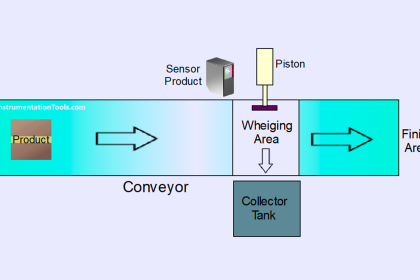
Problem Diagram

Problem Solution
For controlling we used here PID function so according to set point it will automatically control drive speed.
As per name, PID controller consists main three coefficients: proportional, integral and derivative.
For VFD drive control explanation, we will use setpoint for drive from the PLC (50RPM). PID function will maintain the speed as per setting.
According to set point PID will generate output and the VFD drive receives the PLC input and maintains the required motor speed.
Here we are considering 4-20mA signal for VFD drive input (required speed setpoint from PLC) and feedback from the drive is also 4-20mA which in-turn connected to PLC to display the actual speed in HMI.
List of inputs and outputs
Digital Inputs/Analog Inputs
- PID Enable :- I0.0
- Manual Enable :- I0.1
- PID reset :- I0.2
- 4-20mA signal form drive :- IW64
Digital outputs/Analog output
- Analog output for drive :- QW80
M memory
- Set point PID :- MD500
- PID output for drive :- MW762
- Run mode by startup :- M0.3
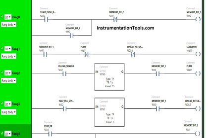
PLC Ladder diagram to control motor speed
PLC Program Explained
For this application, we use S7-1200 PLC and TIA portal software for programming. We can implement this logic by using other PLC also.
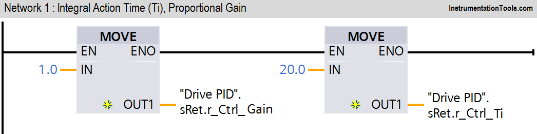
Network 1:
In network we configured standard parameters for PID function.
- “Drive PID”.sRet.r_Ctrl_Gain:- saved proportional gain or P gain for PID (1.0).
- “Drive PID”.sRet.r_Ctrl_Ti:-Saved integral time or I gain for PID (20s).
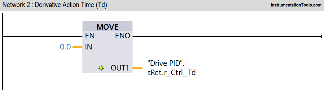
Network 2:
“Drive PID”.sRet.r_Ctrl_Td:-Saved derivative time or D gain for PID (0s).
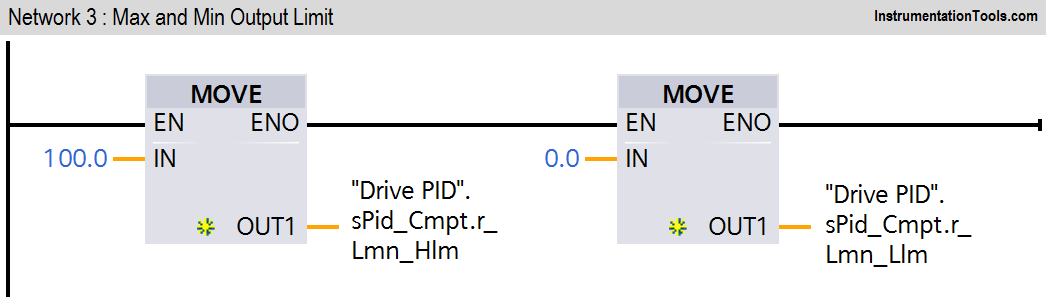
Network 3:
Here we have taken drive PID max output limit and minimum output limit. We have considered here max limit for PID output 100 and minimum limit is 0.
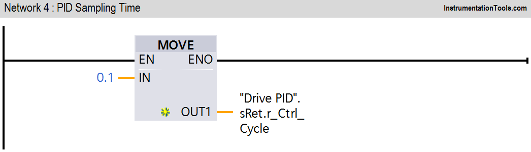
Network 4:
Sampling time of the PID_Compact instruction r_Cycle is determined automatically and usually equivalent to the cycle time of the calling OB. Consider 0.1s for this application.
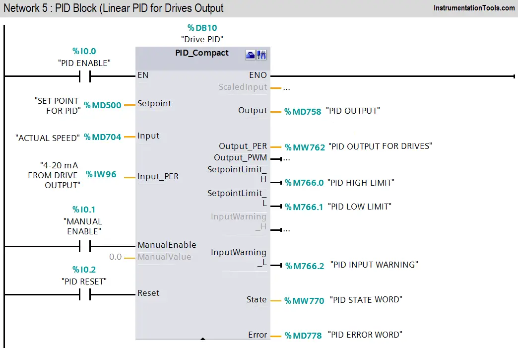
Network 5:
When PID enable (I0.0) is pressed PID block will be executed. As per SET point (MD500) it will generate output (0-27648) and according to speed drive will give feedback (IW96) to PID.Manual enable (I0.1) is for manual operation and PID reset (I0.2) is for resetting the PID.
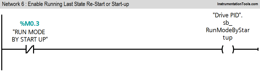
Network 6:
Activate Mode after CPU restart If sb_RunModeByStartup = FALSE, the controller will remain inactive after a CPU startup. After a CPU startup and if sb_RunModeByStartup = TRUE, the controller will return to the most recently active operating mode.
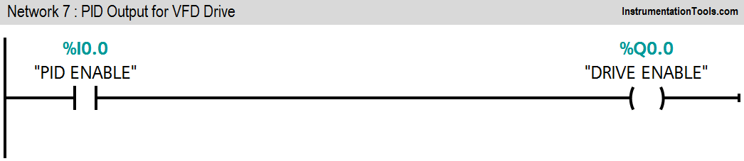
Network 7:
When PID enable switch (I0.0) is pressed, Drive (Q0.0) will be enabled.
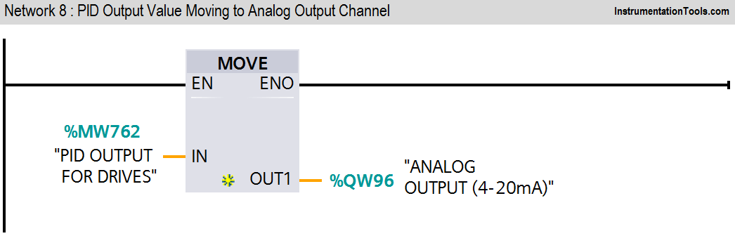
Network 8:
Moving PID output (MW762) to Analog channel (QW96) of the expansion module of the PLC.
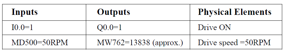
Set 50 RPM form the HMI and enable PID so PID will generate output according to set point. After getting output from PID drive will run on 50 RPM and it will generate mA according to speed. After reaching set point PID will maintain 50 RPM.
In above application we have considered S7-1200 PLC. There are two on board analog inputs (Voltage) in this CPU. So for this application we need consider one more expansion module which has analog input facilities with current range selection.
In TIA portal software, select analog output type > current and range > 4-20mA
Note :- Above application may be different from actual application. This example is only for explanation purpose only. We can implement this logic in other PLC also. This is the simple concept of drive speed control using PID.
All parameters considered in example are for explanation purpose only, parameters may be different in actual applications.
For PID we need to configure so many parameter, here we configured parameters only for our application. Hence all parameters are not configured here.
Result
If you liked this article, then please subscribe to our YouTube Channel for PLC and SCADA video tutorials.
You can also follow us on Facebook and Twitter to receive daily updates.
Read Next:
- PLC Analog Signals Wiring
- Analog Input Card Resolution
- PLC Interview Questions
- Sensor Scaling in PLC
- PLC Output Types


very good
please, i have a question. what is MD? what is md500? md763?