This is a PLC Program for automatic heating and mixing of products. Learn the PLC programming with this example for engineering students.
Heating and Mixing of Products
Problem Description
Make an automatic system in which two materials are collected in one tank. All materials are to be mixed till they achieve a predefined set point of temperature.
Make a ladder program in S7-1200 PLC for this application.
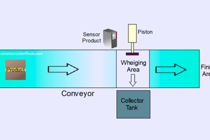
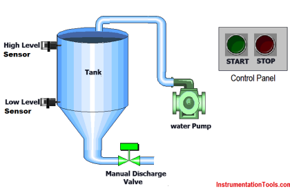
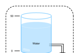
Problem Diagram

Problem Solution
We can solve this problem by using simple logic. For this system consider two separate level switches to detect the level of two different materials (Lets say Material A & Material B).
Also consider one level switch for empty level detection.
For controlling the level we can use single acting valve (fully open and fully close type).
For mixing, agitator is used and it is connected with motor shaft.
Heater and temperature sensor are installed inside the tank.
Here materials are mixed until it reaches the set point of temperature and after mixing, outlet valve (Q0.4) will be operated to drain the mixed products.
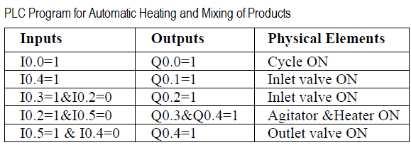
List of Inputs & Outputs
Inputs List
- Cycle START :- I0.0
- Cycle STOP :- I0.1
- Level of material B :- I0.2
- Level of material A :- I0.3
- Empty level switch :- I0.4
- Temperature sensor :- I0.5
Outputs List
- Inlet valve 1 :- Q0.0
- Inlet valve 2 :- Q0.1
- Agitator motor :- Q0.2
- Heater :- Q0.3
- Outlet valve :- Q0.4
M Memory
- M0.0 :- Cycle ON
PLC Program for heating and mixing of product
Program Explained
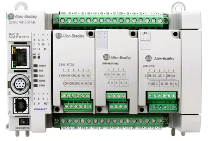
In this problem, we will consider S7-1200 PLC and TIA portal software for programming.
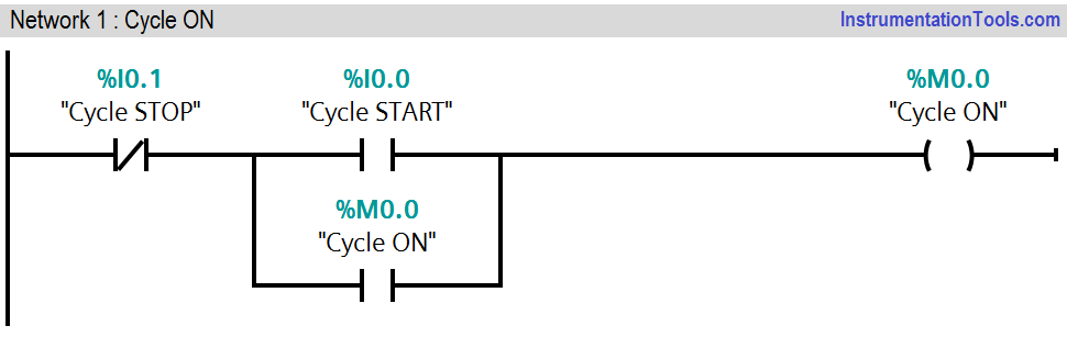
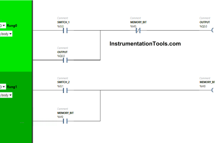
Network 1:
This network shows simple latching circuit for cycle ON and cycle OFF. Normally Open (NO) contact of cycle START button (I0.0) and NC contact of cycle STOP button (I0.1) for cycle activation.
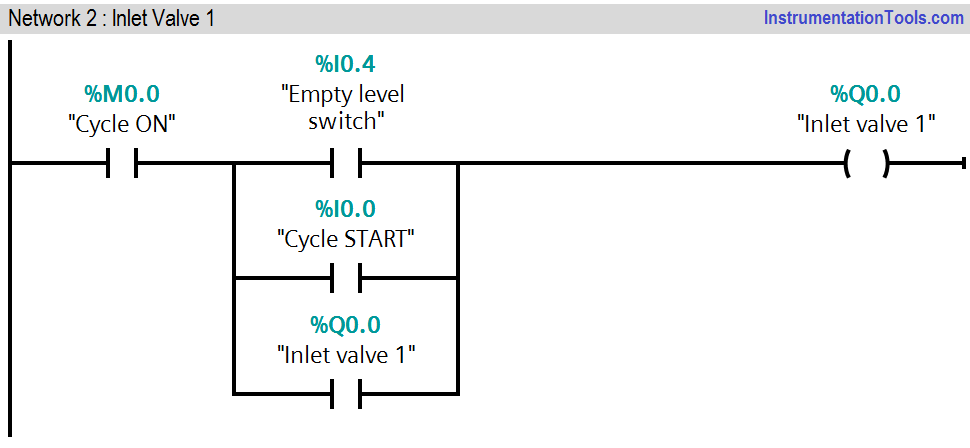
Network 2:
This network is to operate Inlet Valve 1(Q0.0). It is operated when Low Level of the tank is detected (I0.4). And it is closed when Level Material A is detected by a switch with address (I0.3). START PB (I0.0) also connected in parallel so if low level not detected, inlet valve can be started by pressing START PB (I0.0).
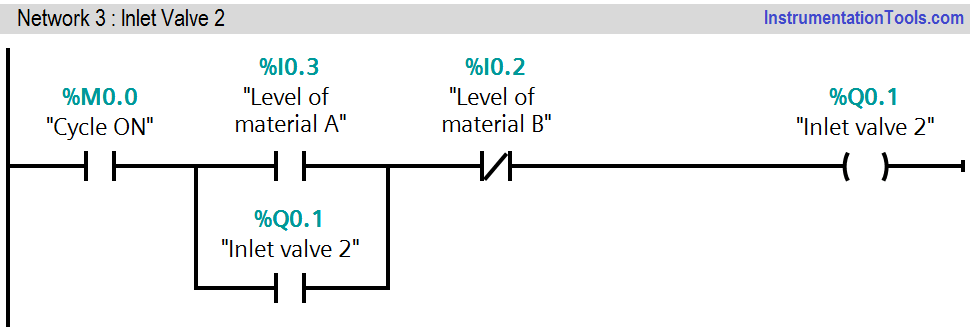
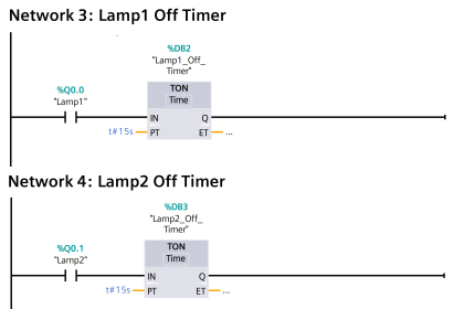
Network 3:
This network is to operate inlet valve 2 (Q0.2).It is operated when material A is filled with its desired level. When cycle is running and level of material A is detected, inlet valve 2 (Q0.1) will be ON.
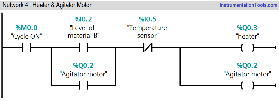
Network 4:
This network is to operate agitator motor and heater. When tank is full with material A and material B, heater (Q0.3) and agitator motor (Q0.2) will be ON.
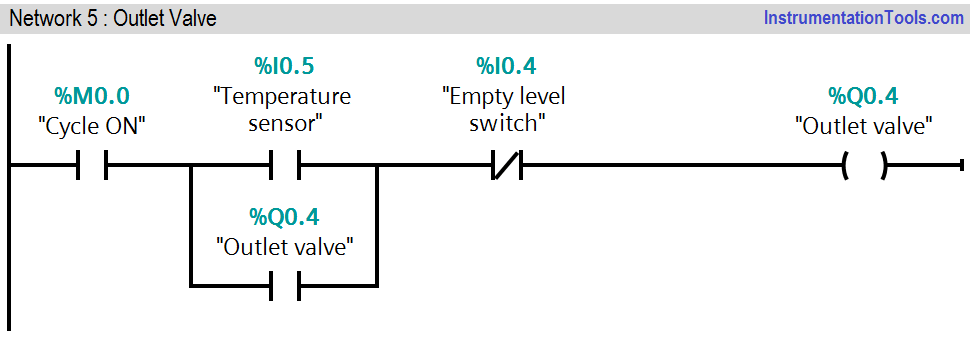
Network 5:
When entire mixing process and heating are completed, outlet valve (Q0.4) will be ON. NC contact of empty level switch (I0.4) is used to stop the outlet valve when tank is empty.
Note :- Above logic is for explanation of certain application only. The diagram is for representation purpose, actual system might be different form this system.
Result
If you liked this article, then please subscribe to our YouTube Channel for PLC and SCADA video tutorials.
You can also follow us on Facebook and Twitter to receive daily updates.
Read Next:
- PLC Star Delta Motor Starter
- Thermostat Temperature Control
- PLC Interposing Relay
- Flow Totalizer using PLC
- Burglar Alarm Security System


Excellent informative
A level switch missing in Network 2
yes I notice it too, I thought it was part of the problem
I will like to get a copy
this one is a good logic . But a real time industrial logic will be very useful . and if the solutions will be using those blocks which are used by professional programmers than that will make my day . 🙂
thanks to admin and publisher
Thanks for the example!
But what will close Valve 1?
Shouldn’t it close once Level Material A has been reached?
The program has been written very good expect one thing. When tank is emptying and the level of the material goes down to the level material B sensor then the valve 2 will open right away same thing will happen with valve 1. To avoid this one you need to make a program in a way so when tank become full empty then and then it starts the whole process again. Just add NC contact of empty level sensor in network 2 and network 3.
Yes, and you are missing level switch in network 2 as well. You can use either NC of outlet valve or NC of empty level sensor in network 2 and network 3.
My apology, you can use only NC of outlet valve because if you use NC of empty level switch it will never turn on the valve B for the first cycle so you can use only NC of outlet valve.