Inst ToolsInst ToolsInst Tools
  • Courses
  • Automation
    • PLC
    • Control System
    • Safety System
    • Communication
    • Fire & Gas System
  • Instrumentation
    • Design
    • Pressure
    • Temperature
    • Flow
    • Level
    • Vibration
    • Analyzer
    • Control Valve
    • Switch
    • Calibration
    • Erection & Commissioning
  • Interview
    • Instrumentation
    • Electrical
    • Electronics
    • Practical
  • Q&A
    • Instrumentation
    • Control System
    • Electrical
    • Electronics
    • Analog Electronics
    • Digital Electronics
    • Power Electronics
    • Microprocessor
  • Request
Search
  • Books
  • Software
  • Projects
  • Process
  • Tools
  • Basics
  • Formula
  • Power Plant
  • Root Cause Analysis
  • Electrical Basics
  • Animation
  • Standards
  • 4-20 mA Course
  • Siemens PLC Course
Reading: PLC Crane Movement Control with Limit Switches
Share
Notification Show More
Font ResizerAa
Inst ToolsInst Tools
Font ResizerAa
  • Courses
  • Design
  • PLC
  • Interview
  • Control System
Search
  • Courses
  • Automation
    • PLC
    • Control System
    • Safety System
    • Communication
    • Fire & Gas System
  • Instrumentation
    • Design
    • Pressure
    • Temperature
    • Flow
    • Level
    • Vibration
    • Analyzer
    • Control Valve
    • Switch
    • Calibration
    • Erection & Commissioning
  • Interview
    • Instrumentation
    • Electrical
    • Electronics
    • Practical
  • Q&A
    • Instrumentation
    • Control System
    • Electrical
    • Electronics
    • Analog Electronics
    • Digital Electronics
    • Power Electronics
    • Microprocessor
  • Request
Follow US
All rights reserved. Reproduction in whole or in part without written permission is prohibited.
Inst Tools > Blog > PLC Tutorials > PLC Crane Movement Control with Limit Switches

PLC Crane Movement Control with Limit Switches

Learn how to control crane movement with limit switches using the CX-Programmer software in the OMRON PLC system.

Last updated: September 30, 2024 4:50 pm
Editorial Staff
PLC Tutorials
No Comments
Share
6 Min Read
SHARE

This article discusses the PLC program to control crane movement using the OMRON PLC in CX-Programmer software. In this PLC program, the Trolley Part of the Crane can move Left or Right and the Hoist Part of the Crane can move Up or Down. The movement of the Trolley Crane and Hoist Crane must be limited so as not to exceed the safety limit using the Limit Switch. This system allows the Crane to be controlled Up or Down and Left or Right by providing a safety function.

Contents
Program ObjectivePLC I/O AddressingPLC Crane Movement Control

Program Objective

The PLC program has 4 main buttons:

  1. The UP_BUTTON (0.05) is used to move the Hoist Crane Up.
  2. The DOWN_BUTTON (0.04) button is used to move the Hoist Crane Down.
  3. The LEFT_BUTTON (0.02) is used to move the crane to the Left.
  4. The RIGHT_BUTTON (0.03) button is used to move the Crane to the Right.
  5. The EMERGENCY (0.06) button is used to Stop all Crane movement in case of emergency but does not turn OFF the system.

Limit Switch is used as a safety system to prevent the crane from moving beyond the safety limit.

  • LS_UP (0.09) is used to limit the highest position of the Hoist Crane, preventing the Hoist Crane from moving too High.
  • LS_LEFT (0.07) is used to limit the crane’s reach when it moves too far to the Left.
  • LS_RIGHT (0.08) is used to limit the crane’s reach when it moves too far to the Right.
PLC Crane Movement Control with Limit Switches

PLC I/O Addressing

CommentInput (I)Output (Q)Memory Bits
START_SYSTEM0.00  
STOP_SYSTEM0.01  
LEFT_BUTTON0.02  
RIGHT_BUTTON0.03  
DOWN_BUTTON0.04  
UP_BUTTON0.05  
EMERGENCY0.06  
LS_LEFT0.07  
LS_RIGHT0.08  
LS_UP0.09  
OUT_LEFT 100.00 
OUT_RIGHT 100.01 
OUT_DOWN 100.02 
OUT_UP 100.03 
SYSTEM_ON  W0.00
IR_LEFT  W0.01
IR_RIGHT  W0.02
IR_DOWN  W0.03
IR_UP  W0.04

PLC Crane Movement Control

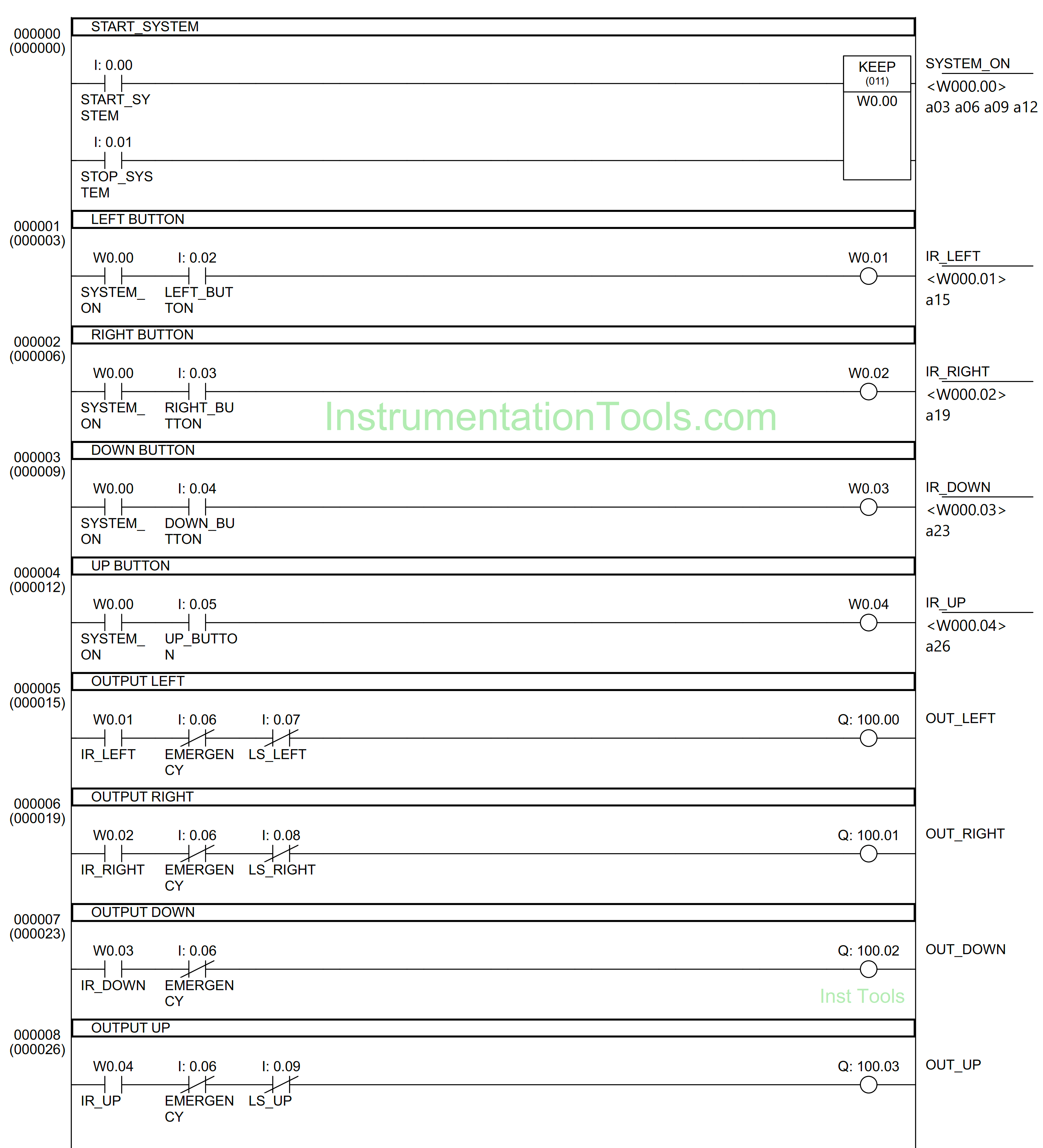
RUNG 0 (START SYSTEM)

In this Rung, when the START_SYSTEM (0.00) button is pressed, the memory bit SYSTEM_ON (W0.00) will be in the HIGH state. Because the KEEP (011) instruction is used, the memory bit SYSTEM_ON (W0.00) remains in the HIGH state even though START_SYSTEM (0.00) button has been Released.

The memory bit SYSTEM_ON (W0.00) will become a LOW state if the STOP_SYSTEM (0.01) button is Pressed.

Trolley and hoist PLC control

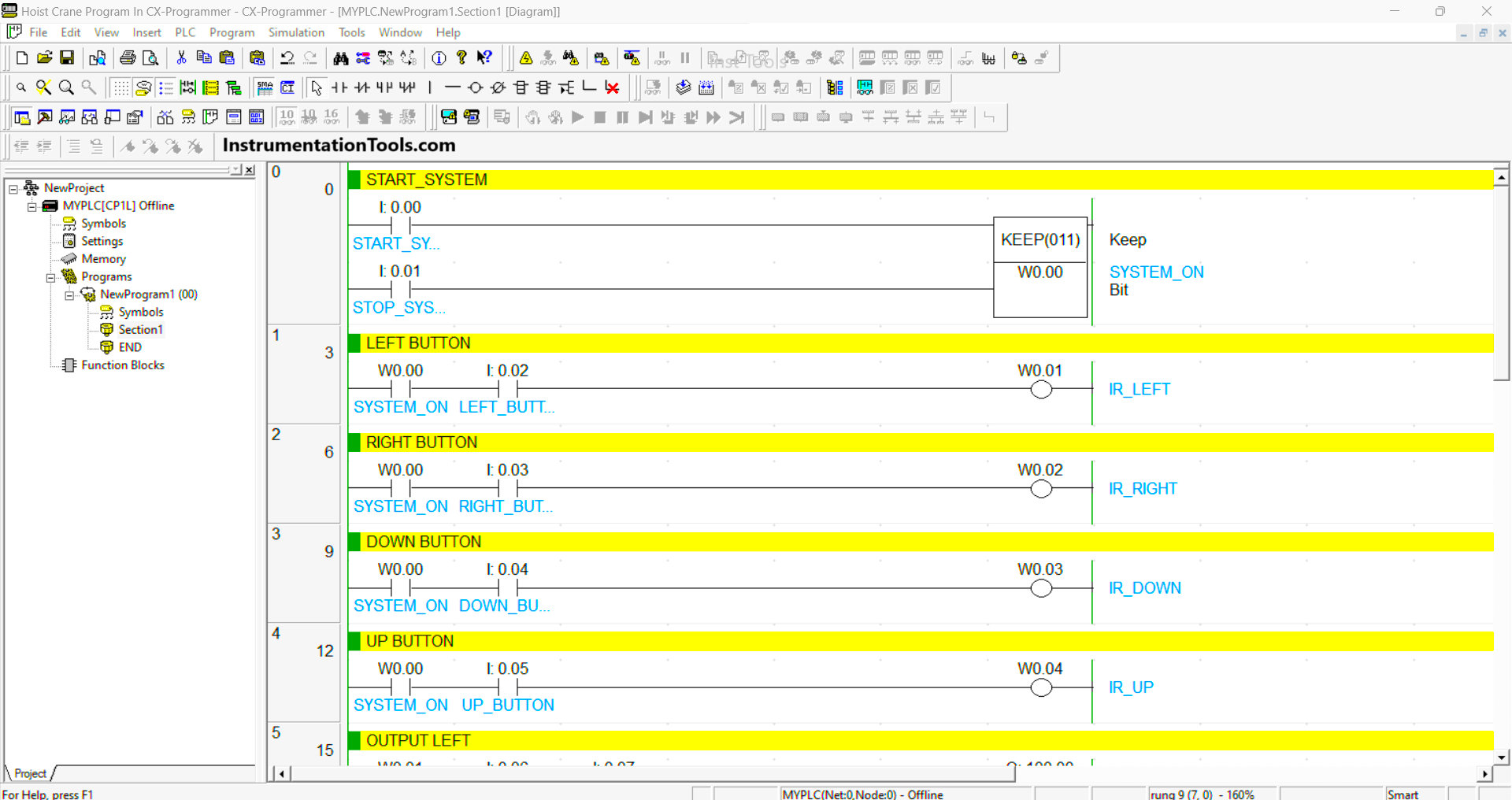
RUNG 1 (LEFT BUTTON)

In this Rung, when the memory bit SYSTEM_ON (W0.00) is in the HIGH state and the LEFT_BUTTON (0.02) button is Pressed, the memory bit IR_LEFT (W0.01) will be in the HIGH state.

RUNG 2 (RIGHT BUTTON)

In this Rung, when the memory bit SYSTEM_ON (W0.00) is in the HIGH state and the RIGHT_BUTTON (0.03) button is Pressed, the memory bit IR_RIGHT (W0.02) will be in the HIGH state.

RUNG 3 (DOWN BUTTON)

In this Rung, when the memory bit SYSTEM_ON (W0.00) is in the HIGH state and the DOWN_BUTTON (0.04) button is pressed, the memory bit IR_DOWN (W0.03) will be in the HIGH state.

RUNG 4 (UP BUTTON)

In this Rung, when the memory bit SYSTEM_ON (W0.00) is in the HIGH state and the UP_BUTTON (0.05) button is pressed, the memory bit IR_UP (W0.04) will be in the HIGH state.

RUNG 5 (LEFT OUTPUT)

In this Rung, Output OUT_LEFT (100.00) will be ON when the NO contact of memory bit IR_LEFT (W0.01) is in the HIGH state. The OUT_LEFT (100.00) output will be OFF if the EMERGENCY (0.06) button is Pressed or if the NC contact of Limit Switch LS_LEFT (0.07) is in the HIGH state.

OMRON PLC crane automation

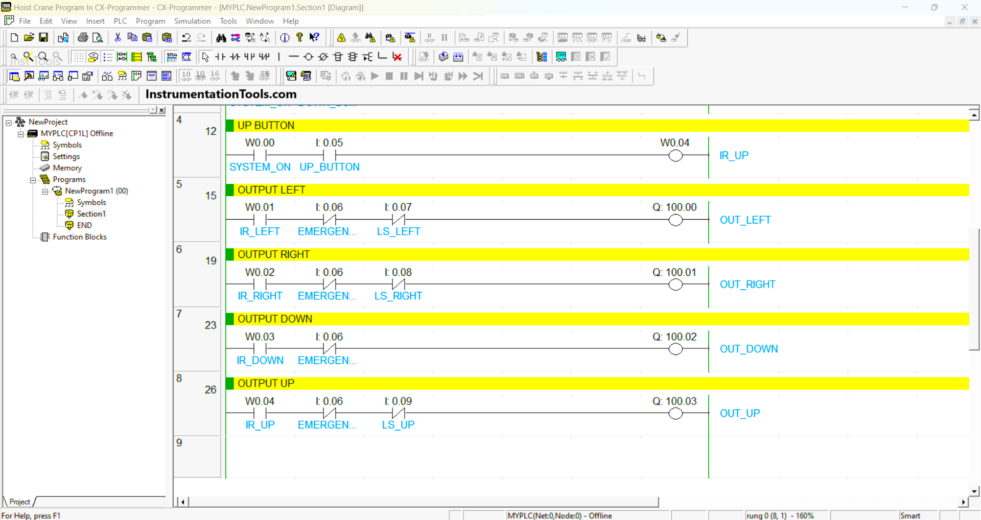
RUNG 6 (OUTPUT RIGHT)

In this Rung, Output OUT_RIGHT (100.01) will be ON when the NO contact of memory bit IR_RIGHT (W0.02) is in the HIGH state. The OUT_RIGHT (100.01) output will be OFF if the EMERGENCY (0.06) button is Pressed or if the NC contact of Limit Switch LS_RIGHT (0.08) is in the HIGH state.

RUNG 7 (OUTPUT DOWN)

In this Rung, Output OUT_DOWN (100.02) will be ON when the NO contact of memory bit IR_DOWN (W0.03) is in the HIGH state. The OUT_DOWN (100.02) output will be OFF if the EMERGENCY (0.06) button is Pressed.

RUNG 8 (OUTPUT UP)

In this Rung, Output OUT_UP (100.03) will be ON when the NO contact of memory bit IR_UP (W0.04) is in the HIGH state. The OUT_UP (100.03) output will be OFF if the EMERGENCY (0.06) button is Pressed or if the NC contact of Limit Switch LS_UP (0.09) is in HIGH state.

Read Next:

  • PLC Program for Mailbox with Counting
  • Dosing Pump PLC Programming Logic
  • PLC Programming based on Logic Circuit
  • Schneider Electric PLC Timer Problems
  • PLC Programming 3 Motors with Priority

Don't Miss Our Updates
Be the first to get exclusive content straight to your email.
We promise not to spam you. You can unsubscribe at any time.
Invalid email address
You've successfully subscribed !

Continue Reading

Siemens S7-300 CPU Suffix Explanation
Download Allen Bradley RSLogix PLC Software
Free Download Programmable Logic Controller (PLC) Book
Automatic Bottle Filling System using PLC
PID Controller Output Types – PID_PWM and PID_Output
Jump Instruction in Siemens Tia Portal
Share This Article
Facebook Whatsapp Whatsapp LinkedIn Copy Link
Share
Leave a Comment

Leave a Reply Cancel reply

Your email address will not be published. Required fields are marked *

Stay Connected

128.3kFollowersLike
69.1kFollowersFollow
210kSubscribersSubscribe
38kFollowersFollow

Categories

Explore More

4–20 mA Process Control Loops
How to Delay a Sensor Signal in PLC?
What is Human Machine Interface (HMI) ?
DC Injection Braking in VFD
Waste-Burning System OMRON PLC Program Example
PLC Programming Videos
PLC FBD Example for Tank Liquid Heating Control by Steam Flow
OPC in Old PLC Systems

Keep Learning

SCADA Interview Questions

SCADA Interview Questions and Answers

Step-by-step import export in FactoryTalk View

FactoryTalk View Studio – Import and Export Tutorial

Difference Between PLC and SCADA

Difference Between PLC and SCADA

AENT Module in Rockwell PLC

AENT Module in Rockwell PLC – Remote IO Adapter

How to Run Multiple Motors with a Single VFD

How to Run Multiple Motors with a Single VFD?

PLC Code to Start & Stop Motor and Pump as per Logic

PLC Code to Start & Stop Motor and Pump as per Logic

PLC Ladder Logic Example based on Set Coil and Reset Coil

PLC Ladder Logic Example based on Set Coil and Reset Coil

Structured Text PLC Program for Measuring Event Duration

Structured Text PLC Program for Measuring Event Duration

Learn More

CNC Machining Deep Hole Drilling

Deep Hole Drilling Ideal Methods For CNC Machining

Certified Automation Professional (CAP) Exam Questions

Certified Automation Professional (CAP) Exam Questions

One Shot Rising PLC Example Program

One Shot Rising PLC Example Program

Most Asked Questions on Servo Motor

Most Asked Questions on Servo Motor (Answers)

Analog Demodulators Objective Questions

Analog Demodulators Objective Questions

PLC Program to Count and Pack Parts from conveyor

Count and Pack Objects from Conveyor using PLC Ladder Logic

DCS Commissioning Steps

DCS Commissioning Steps

Shutdown Maintenance

The 5 Phases of Conducting Shutdown Maintenance

Menu

  • About
  • Privacy Policy
  • Copyright

Quick Links

  • Learn PLC
  • Helping Hand
  • Part Time Job

YouTube Subscribe

Follow US
All rights reserved. Reproduction in whole or in part without written permission is prohibited.
Welcome Back!

Sign in to your account

Username or Email Address
Password

Lost your password?