In this article, you will learn the PLC code to start & stop motor and pump as per logic and understand the programming basics.
Note: The PLC code example is prepared to understand the basic programming for beginners.
PLC Code
Problem Statement
Design a PLC ladder logic for the following application.
We are using two Push Buttons to control a Motor and Pump.
When the Start Push Button is pressed and released, the Motor will be ON after 15 seconds.
When the Stop Push Button is pressed and released, the Motor will stop immediately and the Pump will Turn ON after 10 seconds.
Hands-On PLC Videos
Try our PLC programming videos to understand the example problems and practice them to get hands-on experience with the software.
Inputs
Digital Inputs
Start Push Button: I0.0
Stop Push Button: I0.1
Outputs
Digital Outputs
Motor: Q0.0
Pump: Q0.1
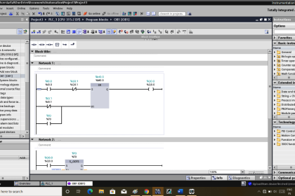
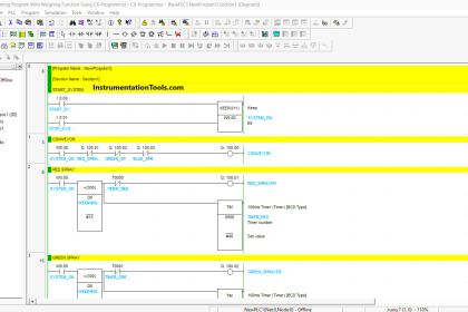
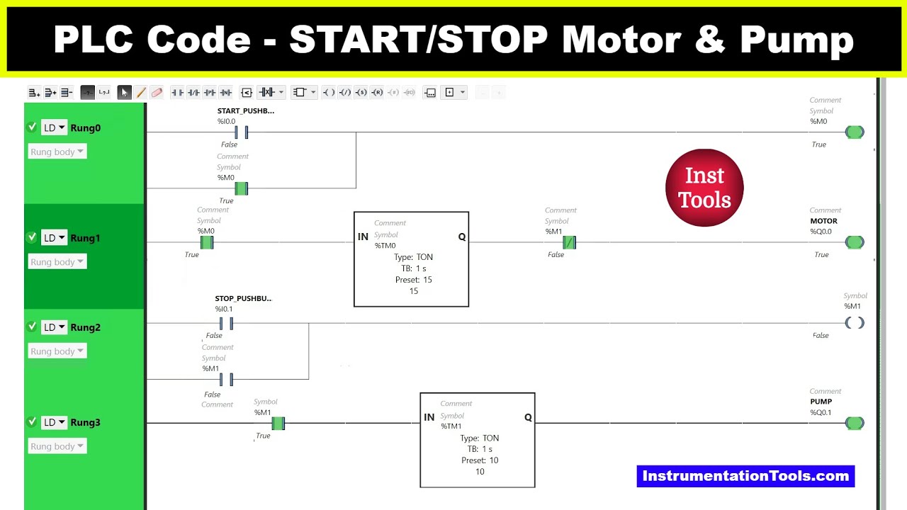
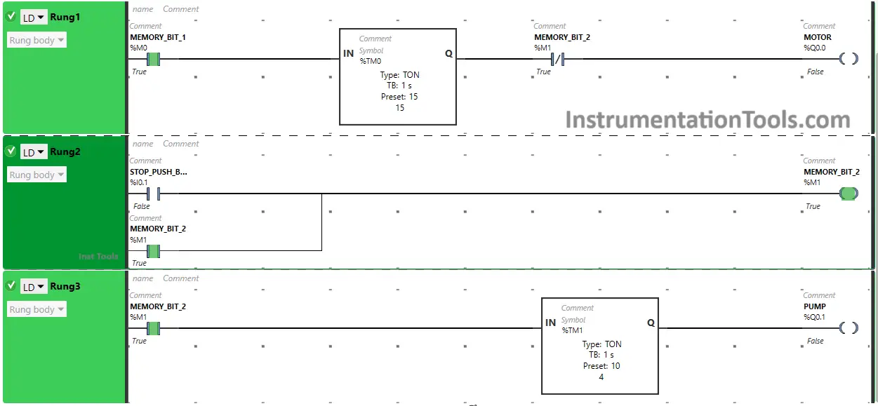
Start & Stop the Motor and Pump Logic
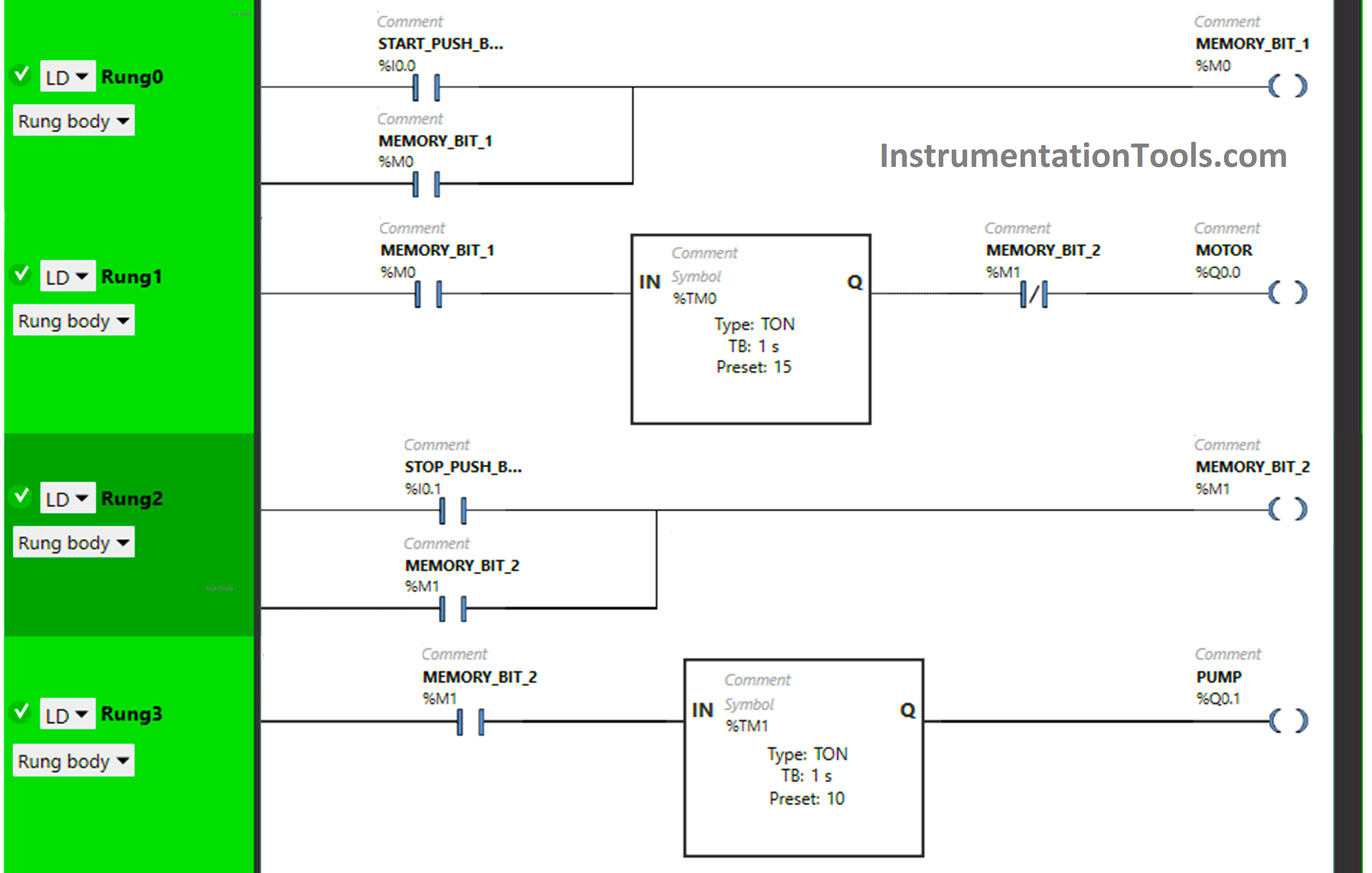
PLC Logic Description
Here we used Normally Open Contact for the Start Push Button, Stop Push Button, and Memory Bits.
Normally Closed Contact is used for Memory Bit 2 in Rung1.
Two Timer Function Block Type TON is used for the Motor and Pump.
In Rung 0:
- Normally Open Contact is used for the Start Push Button to Turn ON Memory Bit 1.
- Latching is used for Memory Bit 1 so that when the Start Push Button is released, Memory Bit 1 still remains ON.
In Rung 1:
- Normally Open Contact is used for Memory Bit 1 to Turn ON Motor.
- Normally Closed Contact is used for Memory Bit 2 to Turn OFF Motor.
- Timer Function Block type TON is used for the Motor to delay the Turning ON time.
In Rung 2:
- Normally Open Contact is used for Stop Push Button to Turn ON Memory Bit 2.
- Latching is used for Memory Bit 2 so that when the Stop Push Button is released, Memory Bit 2 still remains ON.
In Rung 3:
- Normally Open Contact is used for Memory Bit 2 to Turn ON Pump.
- Timer Function Block type TON is used for the Pump to delay the Turning ON time.
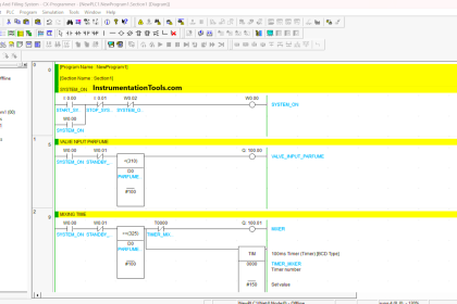
When the Start Push Button is pressed and released, Memory Bit 1 Turns ON in Rung0 and Rung1. when Memory Bit 1 Turns ON in Rung1, the Timer starts in Timer Function Block type TON which is set to 15 seconds and then, it delays 15 seconds to Turn ON the Motor. In a false state, Normally Closed Contact used for Memory Bit 2 also Passes the signal and the Motor will Turn ON after 15 seconds.
When the Stop Push Button is pressed and released, Memory Bit 2 will Turn ON in Rung1, Rung2, and Rung3 as Normally Open Contact is used for the Stop Push Button that allows the signal to pass and Turn ON Memory Bit 2.
When Memory Bit 2 Turns ON, the Motor will Turn OFF immediately because Normally Closed Contact used for Memory Bit 2 in Rungs1 will be in a True state and will not pass the signal to the Motor.
As Memory Bit 2 turns ON in Rung3, Timer starts in Timer Function Block type TON which is set to 10 seconds and then, it delays 10 seconds to Turn ON the Pump and the Pump will Turn ON after 15 seconds.
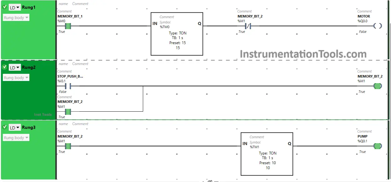
Test Results Overview
Check the below program test results.
When Start Push Button is Pressed and Released
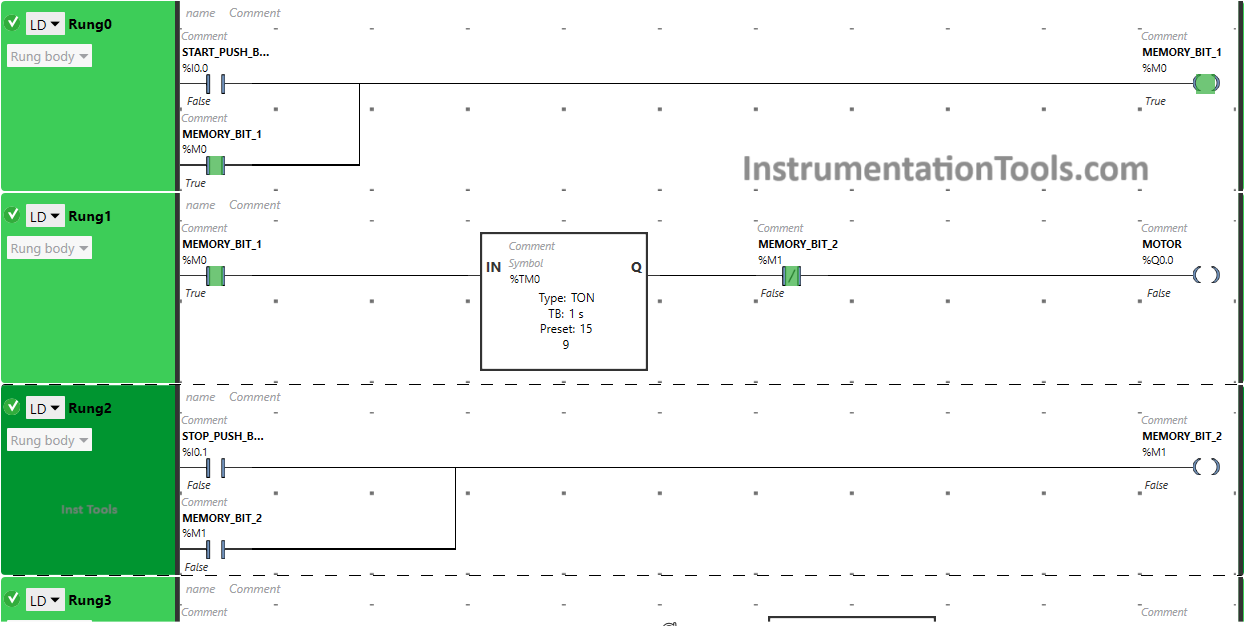
When the Start Push Button is pressed and released, Memory Bit 1 Turns ON in Rung0 and Rung1 as Normally Open Contact is used for the Start Push Button that allows the signal to pass and Turn ON Memory Bit 1.
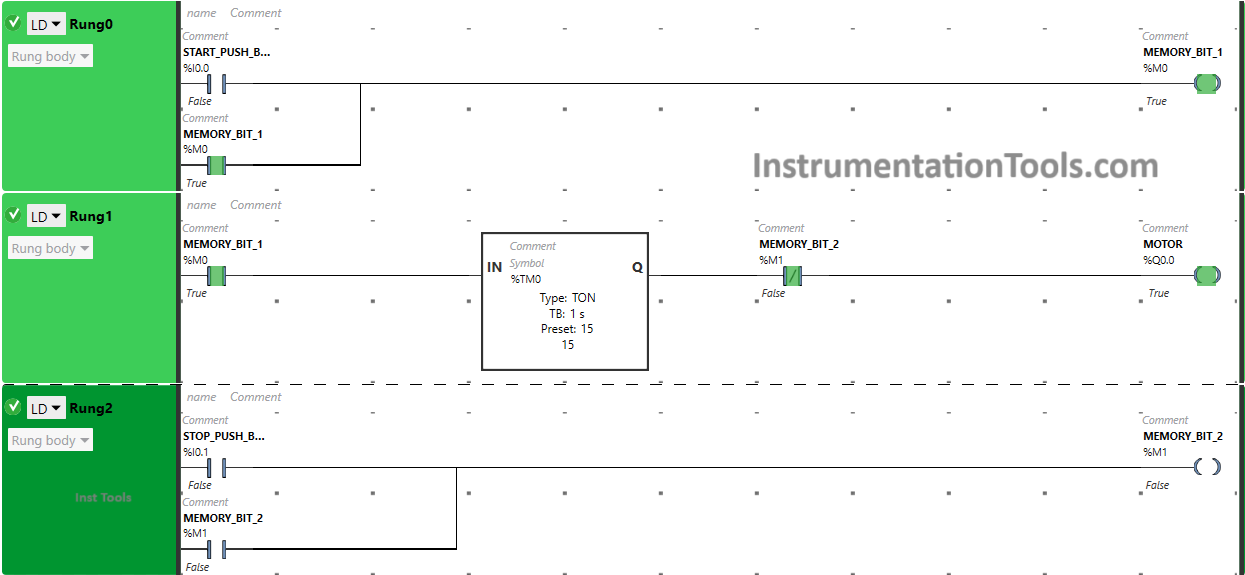
When Memory Bit 1 Turns ON in Rung1, the signal flows through it because Normally Open Contact is used for it and the Timer starts in the Timer Function Block type TON Which delays the time to Turn ON the Motor.
In this Timer Function Block, time is set to 15 seconds. In a false state, Normally Closed Contact used for Memory Bit 2 also Passes the signal and the Motor will Turn ON after 15 seconds.
When Stop Push Button is Pressed and Released
When the Stop Push Button is pressed and released, Memory Bit 2 will Turn ON in Rung1, Rung2, and Rung3 as Normally Open Contact is used for the Stop Push Button that allows the signal to pass and Turn ON Memory Bit 2.
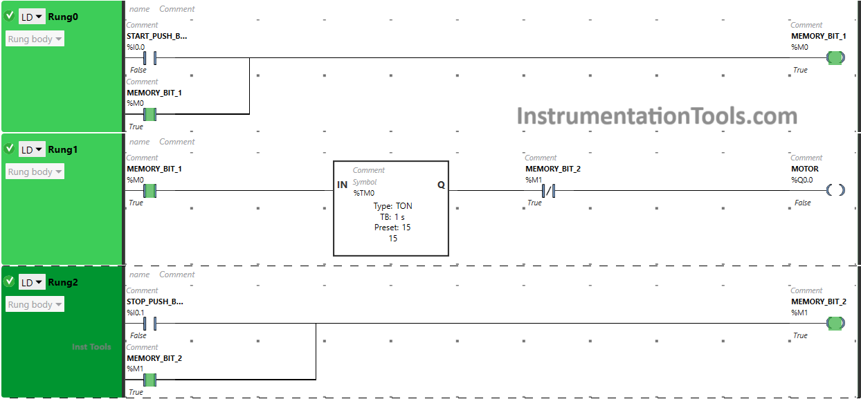
When Memory Bit 2 Turns ON, the Motor will Turn OFF immediately because Normally Closed Contact used for Memory Bit 2 in Rung1 will be in a True state and will not pass the signal to the Motor.
As Memory Bit 2 turns ON in Rung3, the Pump will Turn ON after 10 seconds because Timer Function Block type TON is used for the Pump which delays the time of the Pump to Turn ON.
If you liked this article, please subscribe to our YouTube Channel for PLC and SCADA video tutorials.
You can also follow us on Facebook and Twitter to receive daily updates.
Read Next:
- PLC Automatic Control of Two Outputs
- From Boolean Algebra to PLC Logic
- PLC Program for Solenoid & Pilot Lamp
- PLC Programming Example with Motor
- PLC to Start or Stop using 1 Switch Program