Inst ToolsInst ToolsInst Tools
  • Courses
  • Automation
    • PLC
    • Control System
    • Safety System
    • Communication
    • Fire & Gas System
  • Instrumentation
    • Design
    • Pressure
    • Temperature
    • Flow
    • Level
    • Vibration
    • Analyzer
    • Control Valve
    • Switch
    • Calibration
    • Erection & Commissioning
  • Interview
    • Instrumentation
    • Electrical
    • Electronics
    • Practical
  • Q&A
    • Instrumentation
    • Control System
    • Electrical
    • Electronics
    • Analog Electronics
    • Digital Electronics
    • Power Electronics
    • Microprocessor
  • Request
Search
  • Books
  • Software
  • Projects
  • Process
  • Tools
  • Basics
  • Formula
  • Power Plant
  • Root Cause Analysis
  • Electrical Basics
  • Animation
  • Standards
  • 4-20 mA Course
  • Siemens PLC Course
Reading: PLC Analog Input Scaling
Share
Font ResizerAa
Inst ToolsInst Tools
Font ResizerAa
  • Courses
  • Design
  • PLC
  • Interview
  • Control System
Search
  • Courses
  • Automation
    • PLC
    • Control System
    • Safety System
    • Communication
    • Fire & Gas System
  • Instrumentation
    • Design
    • Pressure
    • Temperature
    • Flow
    • Level
    • Vibration
    • Analyzer
    • Control Valve
    • Switch
    • Calibration
    • Erection & Commissioning
  • Interview
    • Instrumentation
    • Electrical
    • Electronics
    • Practical
  • Q&A
    • Instrumentation
    • Control System
    • Electrical
    • Electronics
    • Analog Electronics
    • Digital Electronics
    • Power Electronics
    • Microprocessor
  • Request
Follow US
All rights reserved. Reproduction in whole or in part without written permission is prohibited.
Inst Tools > Blog > Formulas > PLC Analog Input Scaling

PLC Analog Input Scaling

Last updated: March 4, 2021 4:31 pm
Editorial Staff
Formulas PLC Tutorials
5 Comments
Share
3 Min Read
SHARE

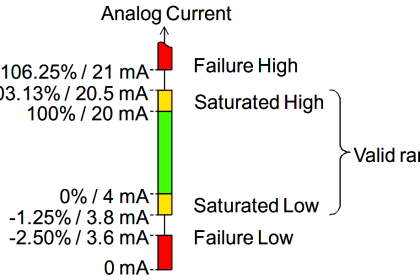
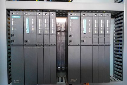
An Allen-Bradley SLC500 programmable logic controller (PLC) uses a 16-bit analog-to-digital converter ( in its model 1746-NI4 ) in analog input card to convert 4-20 mA signals into digital number values ranging from 3277 (at 4 mA) to 16384 (at 20 mA).

However, these raw numbers from the PLC’s analog card must be mathematically scaled inside the PLC to represent real-world units of measurement, in this case 0 to 700 GPM of flow.

PLC Analog Input Scaling

Formulate a scaling equation to program into the PLC so that 4 mA of current registers as 0 GPM, and 20 mA of current registers as 700 GPM.

PLC Analog Input Scaling

We are already given the raw number values from the analog card’s analog-to-digital converter (ADC) circuit for 4 mA and 20 mA: 3277 and 16384, respectively.

These values define the domain of our linear graph:

PLC ADC counts

Calculating and substituting the slope (m) value for this equation, using the full rise-over-run of the linear function:

PLC Scaling Formula

Also Read : PLC Raw Count Calculation

This type of scaling calculation is so common in PLC applications that Allen-Bradley has provided a special SCL (“scale”) instruction just for this purpose.

Instead of “slope” (m) and “intercept” (b), the instruction prompts the human programmer to enter “rate” and “offset” values, respectively.

Furthermore, the rate in Allen-Bradley’s SCL instruction is expressed as the numerator of a fraction where the denominator is fixed at 10000, allowing fractional (less than one) slope values to be specified using integer numbers.

Aside from these details, the concept is exactly the same. Expressing our slope of 700/13107 as a fraction with 10000 as the denominator is a simple matter of solving for the numerator using cross-multiplication and division:

PLC multiplication factor

Thus, the SCL instruction would be configured as follows

PLC SLC instruction Block

Also Read : 4-20mA Conversion Formulas

Credits : by Tony R. Kuphaldt – Creative Commons Attribution 4.0 License

PLC Tutorials :

  • What is Programmable Logic Controller  ?
  • What is Ladder Diagram Programming ?
  • History of Programmable Logic Controllers
  • Mis-conceptions of PLC Ladder Logic
  • Contacts and coils in PLC
  • Digital Input and Output Modules
  • Analog I/O and Network I/O
  • PLC Input/Output Modules
  • Memory Mapping in PLC
  • Analog Input Scaling
  • PLC Example with Switches
  • Counter Instructions
  • Timer Instructions
  • Math instructions
  • Data Instructions
  • Ladder Logic Questions

If you liked this article, then please subscribe to our YouTube Channel for PLC and SCADA video tutorials.

You can also follow us on Facebook and Twitter to receive daily updates.

Don't Miss Our Updates
Be the first to get exclusive content straight to your email.
We promise not to spam you. You can unsubscribe at any time.
Invalid email address
You've successfully subscribed !

Continue Reading

InTouch SCADA Login Password Security
DC Injection Braking in VFD
PID Block in RSLogix 500
Why is RTO used in the Place of TON Timer?
How to choose between PLC and DCS Systems ?
Network Switch Requirement in SCADA and DCS Architecture
Share This Article
Facebook Whatsapp Whatsapp LinkedIn Copy Link
Share
5 Comments
  • youcef says:
    August 11, 2017 at 10:50 am

    thank you

    Reply
  • Sanaullah M. Hasni says:
    July 26, 2019 at 7:42 pm

    Please tell me 4-20 mA is analog input or analog output in plc /Scada system.
    Thanks

    Reply
    • S Bharadwaj Reddy says:
      July 26, 2019 at 8:24 pm

      Always see the signal from control systems point of view.

      Example-

      Field transmitters signal is Analog Input to PLC or DCS.

      PLC or DCS signal to Control Valves is Analog Output.

      Reply
      • Satheesh says:
        December 31, 2019 at 11:06 am

        Sir please injection moulding plc check

        Reply
  • Alex says:
    February 25, 2020 at 8:02 am

    Wow what an information is shared in this platform. I am impressed thank you Inst Tools

    Reply

Leave a Reply Cancel reply

Your email address will not be published. Required fields are marked *

Stay Connected

128.3kFollowersLike
69.1kFollowersFollow
210kSubscribersSubscribe
38kFollowersFollow

Categories

Explore More

What is Process Control?
PLC Simulator using Excel
Difference Between PLC and CNC Machine
Car Wash Program using Functional Block Diagram (PLC)
Basic Pumping System Application Used in Industrial Automation
PLC based Automatic Bell System for a School
PLC Ladder Logic for Lube Oil Pump Motor
How is Data Stored in Standard Modbus Protocol?

Keep Learning

PLC project for traffic signals automation

Complete PLC Project: Traffic Light Auto and Manual Automation

S7 Organizational blocks

Siemens PLC Tia Portal – OB100 Start-up Organization Block

Check Block Consistency Tools

Check Block Consistency Tools in Simatic Manager

High-Speed Inputs in PLC

What are High-Speed Inputs in PLC?

Safety PLC Programming steps

Safety Door Interlock PLC Program

PLC Sequential Lights Control Example

PLC Timer Example: Sequential Control of Three Lights with Reset

What is Hot Standby in PLC

What is Hot Standby in PLC?

SCADA Standards

SCADA for Substation Automation

Learn More

Process vessel for measuring water level

Level Measurement Lab Exercise

Top Electrical Engineering Interview Questions for Freshers

Top Electrical Engineering Interview Questions for Freshers

Construction of Megger

What is a Megger? Principle, Advantages, Disadvantages, Applications

Control Systems Questions & Answers

Control Systems Objective Questions & Answers – Set 7

SCADA Run

PLC Based Industrial Conveyor Ladder Logic

Liquid Level Control using Flow Loop

Liquid Level Control using Flow Loop

Difference between KW and KVA

Difference between KW and KVA

Transmitter Proof Testing

Transmitter Proof Testing

Menu

  • About
  • Privacy Policy
  • Copyright

Quick Links

  • Learn PLC
  • Helping Hand
  • Part Time Job

YouTube Subscribe

Follow US
All rights reserved. Reproduction in whole or in part without written permission is prohibited.
Welcome Back!

Sign in to your account

Username or Email Address
Password

Lost your password?