Inst ToolsInst ToolsInst Tools
  • Courses
  • Automation
    • PLC
    • Control System
    • Safety System
    • Communication
    • Fire & Gas System
  • Instrumentation
    • Design
    • Pressure
    • Temperature
    • Flow
    • Level
    • Vibration
    • Analyzer
    • Control Valve
    • Switch
    • Calibration
    • Erection & Commissioning
  • Interview
    • Instrumentation
    • Electrical
    • Electronics
    • Practical
  • Q&A
    • Instrumentation
    • Control System
    • Electrical
    • Electronics
    • Analog Electronics
    • Digital Electronics
    • Power Electronics
    • Microprocessor
  • Request
Search
  • Books
  • Software
  • Projects
  • Process
  • Tools
  • Basics
  • Formula
  • Power Plant
  • Root Cause Analysis
  • Electrical Basics
  • Animation
  • Standards
  • 4-20 mA Course
  • Siemens PLC Course
Reading: PID Controllers with Output High Select Logic
Share
Font ResizerAa
Inst ToolsInst Tools
Font ResizerAa
  • Courses
  • Design
  • PLC
  • Interview
  • Control System
Search
  • Courses
  • Automation
    • PLC
    • Control System
    • Safety System
    • Communication
    • Fire & Gas System
  • Instrumentation
    • Design
    • Pressure
    • Temperature
    • Flow
    • Level
    • Vibration
    • Analyzer
    • Control Valve
    • Switch
    • Calibration
    • Erection & Commissioning
  • Interview
    • Instrumentation
    • Electrical
    • Electronics
    • Practical
  • Q&A
    • Instrumentation
    • Control System
    • Electrical
    • Electronics
    • Analog Electronics
    • Digital Electronics
    • Power Electronics
    • Microprocessor
  • Request
Follow US
All rights reserved. Reproduction in whole or in part without written permission is prohibited.
Inst Tools > Blog > Control Systems > PID Controllers with Output High Select Logic

PID Controllers with Output High Select Logic

Last updated: August 25, 2019 6:51 pm
Editorial Staff
Control Systems
3 Comments
Share
5 Min Read
SHARE

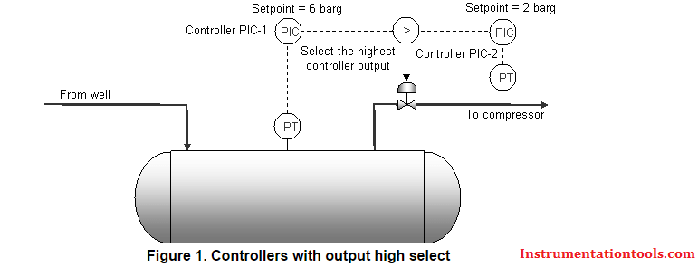
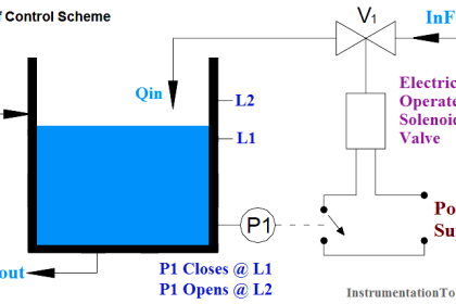
The below figure 1 shows a typical control scheme with two controllers driving the same control valve via high select logic. The controller PIC-1 is the main pressure controller and maintains the vessel pressure of 6 barg by modulation of the control valve.

However, if the suction to the compressors falls below 2 barg for any reason, the suction pressure controller PIC-2 opens up the valve to increase the pressure. So in normal operation, the control valve is controlled by PIC-1 while PIC-2 only takes over if the suction pressure drops too low.

Output High Select Logic

PID Controllers with output high select Logic

Suppose that for the current gas flow rates the control valve is 30% to give the 6 barg vessel pressure. Again suppose that the compressor suction is 3 barg i.e. above the setpoint of PIC-2.

That means that the output of PIC-2 will be decreasing as the controller attempts to close the valve and reduce the pressure. When this output drops below 30%, it has no effect on the valve because the high select logic selects the output of PIC-1 and that controller has full control of the valve.

All well and good, except if the output of PIC-2 carries on dropping all the way to 0%. If for any reason the compressor suction pressure falls away below the setpoint of PIC-2, the control output now has to wind from 0% to 30% before it can start opening the valve to increase the pressure.

By this time, the pressure can easily have decreased even further and possibly have tripped the compressors on low suction pressure.

The above scenario is not at all uncommon and is the cause of many ‘spurious’ trip events. The same argument applies to low select logic except the polarity is reversed: the unselected controller winds up to 100%.

Understandably, the tuning of the controllers is often blamed, but with a little understanding of the problem, it is clear that tuning can not help until the controller has full control of the valve. The main issue is integral wind-up of the controller not currently selected by the high- or low-select logic.

There are several solutions of which the most common are:

  • Clamp the integral of the unselected controller at a value very close (say 2%) to the output of the selected controller. When the unselected controller is needed, it only needs to unwind by 2% rather than all the way from 0% or 100%.
  • When the process variable of the unselected controller approaches the setpoint, ‘bounce’ the output to the same value as the selected controller e.g. by switching the controller momentarily into manual, changing the output and putting it back into automatic again, adjusting the setpoint if necessary.

The first method is straightforward enough to implement on most DCS or PLCs while the second method is suitable when there is no means of applying a limit clamp to the controller integral.

Both techniques have a similar result. In our example above, when the suction pressure drops to the setpoint of PIC-2, the output of the controller is already close to (Method 1) or at (Method 2) the same value as the PIC-1 output, so PIC-2 can immediately take control of the valve which opens up to maintain the pressure.

The controllers should be tuned one at a time by adjusting the setpoints and pressures so that the controller being tuned has full control of the valve: the other controller must be pushed somewhere out of the way and maybe even left in manual.

Otherwise, use normal tuning methods to calculate the controller parameters. Once satisfied with the tuning, thoroughly test the changeover from one controller to the other.

Also Read: Direct Acting vs Reverse Acting Controllers

Don't Miss Our Updates
Be the first to get exclusive content straight to your email.
We promise not to spam you. You can unsubscribe at any time.
Invalid email address
You've successfully subscribed !

Continue Reading

What is a Signal Isolator? Principle, Advantages, Disadvantages
100+ Questions and Answers on Industrial Automation and Control
Integral Controller Principle
Interconnection between PLC, MCC, LCP & Pumps – Video
Augmented Reality and Virtual Reality in Industrial Automation
What is a Transducer ?
Share This Article
Facebook Whatsapp Whatsapp LinkedIn Copy Link
Share
3 Comments
  • go says:
    March 31, 2016 at 4:43 am

    why we can not copy info here? here are many words we do not know their meaning ,we need to translate them.

    Reply
    • S Bharadwaj Reddy says:
      April 3, 2016 at 4:08 am

      Hello, Plz use print button which is available below the Article heading. Thanks

      Reply
  • Vinothkumar says:
    May 26, 2016 at 1:47 pm

    Why vibrational sensor assembly at -7.0 or -10 value use to pump ?

    Reply

Leave a Reply Cancel reply

Your email address will not be published. Required fields are marked *

Stay Connected

128.3kFollowersLike
69.1kFollowersFollow
210kSubscribersSubscribe
38kFollowersFollow

Categories

Explore More

Difference between Router, Switch, and Hub
Types of Cathodic Protection for Pipeline Protection
Instrumentation Engineer Activities & Documents – Detail Design Phase
Flexible Input Output Modules
How-to Create Instrument Loop Diagram (ILD)?
What is PCS 7?
Yokogawa DCS System Maintenance Procedures
Hardware Troubleshooting Steps for PLC Automation Systems

Keep Learning

Cyber Security Multiple Choice Questions and Answers

Cyber Security Multiple Choice Questions and Answers

Layer-2 and Layer-3 Network Switches

Layer-2 and Layer-3 Network Switches

Design & Construction of Process Plant

Process Control Systems Philosophy Concept

Split Range in Foundation Fieldbus

Foundation Fieldbus Split Range Valves

Electrical Circuit Label Schematic

Label the Electrical Circuit Schematic

Definitions of Electrical Grounding

Definitions of Electrical Grounding

Hot Well Level Control System in Condensing Turbine

Hot Well Level Control System in Condensing Turbine

DCS Commissioning Steps

DCS Commissioning Steps

Learn More

Flow Measurement Multiple Choice Questions

Flow Measurement Multiple Choice Questions

Deluge Valve Operation using Solenoid Valve Animation

Deluge Valve Operation

Function Block Diagram - Studio 5000 Logix Designer

Define the Order of Execution in Functional Block Diagram of Studio 5000

stepper motors Animation

Fundamentals of DC Motor Animation

Process Control Instrumentation Engineering Interview Questions

Process Control Instrumentation Engineering Interview Questions

Industrial Sensors

Sensors Handbook

SinkingOutput

Difference Between the Sinking and Sourcing?

steadily pour a liquid into vertical tube

Vertical Tube Liquid Level Equilibrium

Menu

  • About
  • Privacy Policy
  • Copyright

Quick Links

  • Learn PLC
  • Helping Hand
  • Part Time Job

YouTube Subscribe

Follow US
All rights reserved. Reproduction in whole or in part without written permission is prohibited.
Welcome Back!

Sign in to your account

Username or Email Address
Password

Lost your password?