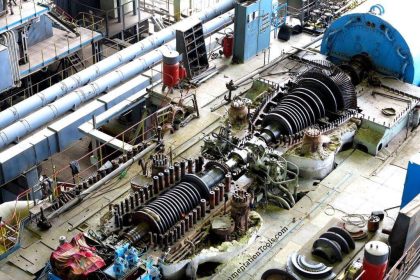
Parts and functions of steam turbine:
- Rotor
- Stem chest
- Casing
- Over speed trip system
- Governor system

Steam chest and the casing
Connected to higher pressure steam supply line and the low pressure steam exhaust line respectively. The steam chest connected to casing, houses the governor valve and the over speed trip valve. The casing contains the rotor and nozzles through which the steam is expanded and directed against the rotating buckets.
Rotor
Consists of shaft and disk assemblies with buckets. The shaft extends beyond the casing through the bearing cases. One end of the shaft is used for coupling to the driven pump. The other end of the shaft serves the speed governor and the over speed trip system.
The bearing cases
Supports the rotor and assemble casing and steam chest. The bearing cases contain the journal bearings and the rotating oil seals, which prevent outward oil leakage and the entrance of water, dust, and steam.
The steam end bearing case contains the rotor positioning bearing and the rotating components of the over speed trip system. An extension of the steam end bearing housing enclose the rotating components of the speed – governor system.
Casing sealing glands
Seal the casing and the shaft. Spring backed segmental carbon rings used for this and supplemented by a spring backed labyrinth section for higher exhaust-steam.
Governor system
Governor systems are speed-sensitive control systems that are integral with the steam turbine. The turbine speed is controlled by varying the steam flow through the turbine by positioning the governor valve. Consists of spring-opposed rotating weights, a steam valve, and an interconnecting linkage or servo motor system. The governor sense turbine shaft speed through direct connection, worm/worm wheel, or magnetic impulse from a gear.
The turbine speed is compared to some predetermined set point and the governor output signal to a servo motor. Change in the turbine inlet and exhaust-steam conditions, and the power required by the pump will cause the turbine speed to change. The change in speed results in repositioning the governor weights and subsequent repositioning of the governor valve.
Over speed trip system
The trip mechanism acts independently of the governor controlled system and closes the trip valve to stop the flow of steam to the turbine in the event of over speed condition. Consists of a spring-loaded pin or weight mounted in the turbine shaft on a collar, a quick-closing valve which is separate from the governor valve and interconnecting linkage. The centrifugal force created by rotation of the pin in the turbine shaft exceeds the spring loading at a preset speed.
The resultant movement of the trip pin causes knife-edges in the linkage to separate and permit the spring loaded trip valve to close. Over speed governors is arranged to trip at 10 percent over normal speed actuating a quick closing stop valve to shut off the steam supply to the turbine.
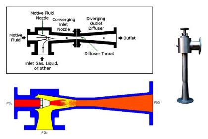
Labyrinth seal
Labyrinth is a means of reducing leakage from high pressure side to low pressure side by allowing a small amount of leakage. The clearance between labyrinth and shaft is kept at the minimum possible. Gases enter the narrow passage between shaft and labyrinth expand because of space available in the first space resulted to less pressure p1 from p.
Similarly the gases enter second space through the restricted passage and expand to less pressure. Thus in last stage, the pressure will be on slightly above atmospheric which will be very small. Thus labyrinths are used for minimizing leakage of gases from high pressure side to low pressure side.
Carbon ring seals
Consists of carbon ring segments and these segments held together by retaining spring. Anti rotation stops fit in the notches in the bottom half interstage diagrams (casing) and carbon rings prevents the rotation.
Nozzle ring and reversing blade assembly
The nozzle ring is bolted to the inside bottom half of the steam end casing. The nozzles located in the nozzle ring, direct the steam flow from the steam chest to the Curtis stage first row blades. The reversing blade assembly is located between the blade rows of the Curtis stage (the Curtis stage has two rows of blades) and is bolted to the nozzle ring.
The reversing blades reverse the steam flow as it exits the first row of blades and directs the steam into the second row of blades of the Curtis stage. The reversing blade assembly is positioned axially by spacers.
Diaphragms:
Stationary diaphragms separate the inner stages, contain the interstage nozzles and interstage seals. The nozzle expand the steam and direct it against the following rows of rotating blades. The diaphragms are adjusted on assembly to allow for rotor deflection and to assure that the seals are concentric with the shaft.
The bottom half of diaphragms are located vertically in the casing grooves by shims at the bottom of the grooves and laterally by means of adjusting screws at the horizontal joint. The top halves of the diaphragms are fixed in the casing by the same arrangement and lift with the casing cover.
Sentinel valve
This is warning device located on the top of the exhaust end turbine casing, indicates excessive turbine exhaust end casing pressure. In the event the casing pressure exceeds a predetermined setting above the normal operating pressure, the valve releases a small amount of visible steam to the atmosphere, causing an audible sound. This valve will not serve as a relief valve.
Auxiliary steam valves
Auxiliary valves are used to achieve more efficient operation with varying load or steam conditions. The valves are provided in the steam passage way (in the bottom half of the steam end turbine casing) between the steam chest and nozzle ring.
The passage is cast in three separate compartments. One compartment is continuously open for steam flow to a bank of nozzles in the nozzle ring. The other two are fitted with auxiliary hand valves to control the flow of steam to two other banks of nozzles in the same nozzle ring.
Turning Gears
Large turbines are equipped with turning gears to rotate the rotors slowly during warm up, cool off. This is to maintain the shaft or rotor at an approximately uniform temperature circumferentially, so as to maintain straightness and preserve the balance.