Inst ToolsInst ToolsInst Tools
  • Courses
  • Automation
    • PLC
    • Control System
    • Safety System
    • Communication
    • Fire & Gas System
  • Instrumentation
    • Design
    • Pressure
    • Temperature
    • Flow
    • Level
    • Vibration
    • Analyzer
    • Control Valve
    • Switch
    • Calibration
    • Erection & Commissioning
  • Interview
    • Instrumentation
    • Electrical
    • Electronics
    • Practical
  • Q&A
    • Instrumentation
    • Control System
    • Electrical
    • Electronics
    • Analog Electronics
    • Digital Electronics
    • Power Electronics
    • Microprocessor
  • Request
Search
  • Books
  • Software
  • Projects
  • Process
  • Tools
  • Basics
  • Formula
  • Power Plant
  • Root Cause Analysis
  • Electrical Basics
  • Animation
  • Standards
  • 4-20 mA Course
  • Siemens PLC Course
Reading: Parallel Open Circuit Faults
Share
Font ResizerAa
Inst ToolsInst Tools
Font ResizerAa
  • Courses
  • Design
  • PLC
  • Interview
  • Control System
Search
  • Courses
  • Automation
    • PLC
    • Control System
    • Safety System
    • Communication
    • Fire & Gas System
  • Instrumentation
    • Design
    • Pressure
    • Temperature
    • Flow
    • Level
    • Vibration
    • Analyzer
    • Control Valve
    • Switch
    • Calibration
    • Erection & Commissioning
  • Interview
    • Instrumentation
    • Electrical
    • Electronics
    • Practical
  • Q&A
    • Instrumentation
    • Control System
    • Electrical
    • Electronics
    • Analog Electronics
    • Digital Electronics
    • Power Electronics
    • Microprocessor
  • Request
Follow US
All rights reserved. Reproduction in whole or in part without written permission is prohibited.
Inst Tools > Blog > Electrical Theory > Parallel Open Circuit Faults

Parallel Open Circuit Faults

Last updated: July 25, 2018 8:13 pm
Editorial Staff
Electrical Theory
No Comments
Share
1 Min Read
SHARE

Faults within a DC circuit will cause various effects, depending upon the nature of the fault. An understanding of the effects of these faults is necessary to fully understand DC circuit operation.

Parallel Open Circuit

A parallel circuit has more than one path for current to flow. If one of the paths is opened, current will continue to flow as long as a complete path is provided by one or more of the remaining paths. It does not mean that you cannot stop current flow through a parallel circuit by opening it at one point; it means that the behavior of a parallel circuit depends on where the opening occurs (Figure 54).

Parallel Open Circuit Fault

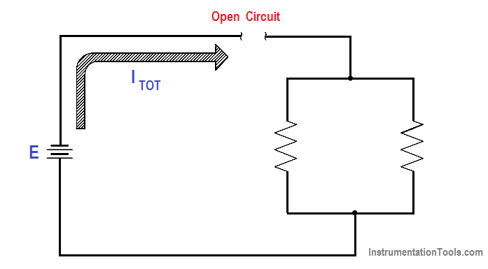
Figure 54 : Open Parallel Circuit – Total

If a parallel circuit is opened at a point where only a branch current flows, then only that branch is open, and current continues to flow in the rest of the circuit (Figure 55).

Parallel Open Circuit Fault at branch

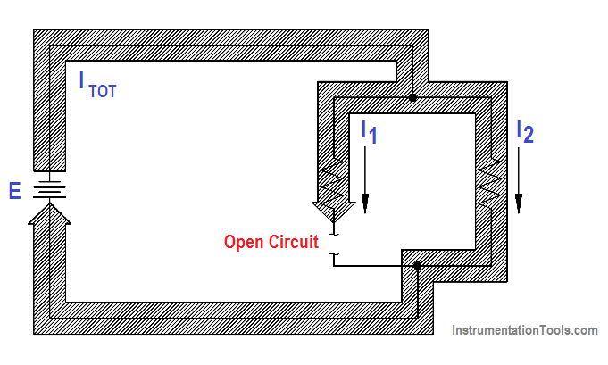
Figure 55 : Open Parallel Circuit – Branch

Don't Miss Our Updates
Be the first to get exclusive content straight to your email.
We promise not to spam you. You can unsubscribe at any time.
Invalid email address
You've successfully subscribed !

Continue Reading

Series Open Circuit Faults
What is Electricity ?
Parallel Circuit Current Calculations
Electric Circuit : Open & Short Circuits
Capacitive Time Constant
Ground Detector Principle
Share This Article
Facebook Whatsapp Whatsapp LinkedIn Copy Link
Share
Leave a Comment

Leave a Reply Cancel reply

Your email address will not be published. Required fields are marked *

Stay Connected

128.3kFollowersLike
69.1kFollowersFollow
210kSubscribersSubscribe
38kFollowersFollow

Categories

Explore More

Y and Delta Resistor Network Calculations
Power Factor
Three Phase Systems
Battery Operation : Series and Parallel
Parallel Circuit
DC Motor Speed
Multimeter & Megger Principle
AC Generator Voltage Regulators

Keep Learning

Battery Interview QuBattery Interview Question and Answersestion and Answers

Battery Terminology

Using Kirchhoff’s Voltage Law to find Current with one Source

Applying Kirchhoff’s Voltage Law

Gang Switch Principle

Reading Electrical Schematics

Transformer Operation Under No-Load

Transformer Operation Under No-Load

Induced EMF

Magnetic Circuits

Generator Action in a Motor

What is Synchroscope ?

Schematic Diagram

Schematic Diagram

Transformer Efficiency and Loses Formula

Transformer Losses and Efficiency

Learn More

Fence grounding specifications

All About Electric Fence Gates

foundation-fieldbus-vs-profibus

Comparison between Foundation Fieldbus and Profibus

Power Electronics Objective Questions

Type D Chopper Objective Questions

Pyrometer Principle

Optical Pyrometer Working Principle Animation

Gas Detectors Practical Problems and Troubleshooting

Gas Detectors Practical Problems and Troubleshooting

Instrumentation Technical Interview Questions and Answers

Instrumentation Technical Interview Questions and Answers

Power Systems Questions & Answers

Power Systems MCQ Series 17

RTD Connection Diagram

Difference Between 2 wire RTD, 3 wire RTD, and 4 wire RTD’s

Menu

  • About
  • Privacy Policy
  • Copyright

Quick Links

  • Learn PLC
  • Helping Hand
  • Part Time Job

YouTube Subscribe

Follow US
All rights reserved. Reproduction in whole or in part without written permission is prohibited.
Welcome Back!

Sign in to your account

Username or Email Address
Password

Lost your password?