Several standards exist for orifice pressure tap locations. Ideally, the upstream pressure tap will detect fluid pressure at a point of minimum velocity, and the downstream tap will detect pressure at the vena contracta (maximum velocity).
In reality, this ideal is never perfectly achieved.
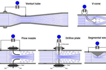
Orifice Plate Tapping
An overview of the most popular tap locations for orifice plates is shown in the following illustration:

Orifice Tap Location

Flange Taps
Flange taps are the most popular tap location for orifice meter runs on large pipes in the United States.
Flanges may be manufactured with tap holes pre-drilled and finished before the flange is even welded to the pipe, making this a very convenient pressure tap configuration.
Most of the other tap configurations require drilling into the pipe after installation, which is not only labor-intensive, but may possibly weaken the pipe at the locations of the tap holes.
Vena contracta taps
Vena contracta taps offer the greatest differential pressure for any given flow rate, but require precise calculations to properly locate the downstream tap position.
Radius taps are an approximation of vena contracta taps for large pipe sizes (one-half pipe diameter downstream for the low-pressure tap location).
An unfortunate characteristic of both these taps is the requirement of drilling through the pipe wall.
Not only does this weaken the pipe, but the practical necessity of drilling the tap holes in the installed location rather than in a controlled manufacturing environment means there is considerable room for installation error.
Corner taps
Corner taps must be used on small pipe diameters where the vena contracta is so close to the downstream face of the orifice plate that a downstream flange tap would sense pressure in the highly turbulent region (too far downstream).
Corner taps obviously require special (i.e. expensive) flange fittings, which is why they tend to be used only when necessary.
Care should be taken to avoid measuring downstream pressure in the highly turbulent region following the vena contracta. This is why the pipe tap (also known as full-flow tap) standard calls for a downstream tap location eight pipe diameters away from the orifice: to give the flow stream room to stabilize for more consistent pressure readings.
Wherever the taps are located, it is vitally important that the tap holes be completely flush with the inside wall of the pipe or flange.
Even the smallest recess or burr left from drilling will cause measurement errors, which is why tap holes are best drilled in a controlled manufacturing environment rather that at the installation site where the task will likely be performed by nonexperts.
Orifice Plate Taps
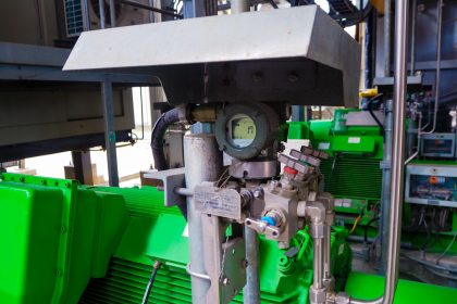
A photograph of an orifice plate used to measure the flow of natural gas to a large turbine engine is shown here, with a Rosemount model 3051 differential pressure transmitter sensing the pressure drop generated by the orifice:

Flange taps are used in this orifice installation, with the taps and pressure transmitter located above the pipe center-line to avoid picking up any liquid droplets that may pass through the pipe.
The direction of gas flow in this particular installation is from left to right, making the left-hand pressure tap the “high pressure” side and the right-hand pressure tap the “low pressure” side.
As you can see by the pressure gauge’s indication in the photograph, the static line pressure of the natural gas inside the pipe is over 300 PSI. The amount of pressure drop generated by the orifice plate at full flow, however, is likely only a few PSI (100 inches water column is typical for many orifice plate installations).
This is why we must use a differential pressure transmitter to measure the orifice plate’s pressure drop: only a DP transmitter will sense the difference in pressure across the orifice while rejecting the static (common-mode) line pressure inside the pipe.
Orifice Plate with Flange Taps
A photograph of another orifice plate with flange taps appears here, shown on a vertical pipe. In this example, the pipe and flanges are formed of acrylic (transparent plastic):
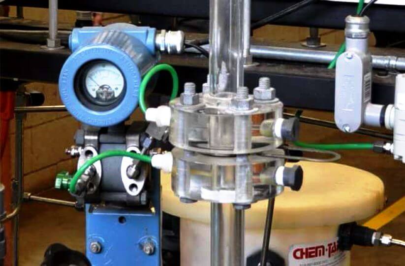
As is customary with orifice plates mounted in vertical pipes, the direction of flow is upward (from bottom to top), making the bottom tap the “high pressure” side and the top tap the “low pressure” side.
Since this is a liquid application, the transmitter is located below (Note) the taps in order to avoid collecting bubbles of air or other gases in the impulse lines.
Note : One installation error seen in this photograph is a green plastic impulse tube with a bend extending above the upper flange tap. Any elevated portion of the impulse tube system will tend to collect gas bubbles over time, possibly causing measurement errors.
A better installation would ensure the impulse tubes never extend above the flange tap they connect to on the liquid-bearing pipe.
This particular orifice and flow transmitter (Rosemount model 1151) is used on a process “trainer” unit at Brazosport College in Lake Jackson, Texas.
The transparent flanges, pipes, and process vessels make it easier for students to visualize the fluid motion.
For relatively low flow rates, an alternative arrangement is the integral orifice plate. This is where a small orifice plate directly attaches to the differential pressure-sensing element, eliminating the need for impulse lines.
Integral orifice plate
A photograph of an integral orifice plate and transmitter is shown here, in an application measuring the flow of purified oxygen gas through a copper pipe:

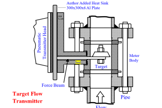
Even smaller integral orifices exist for the measurement of very low flow rates, another type of integral orifice is available. This style uses the pass-through nature of a typical differential pressure transmitter’s capsule flanges to advantage.
Note the paths of fluid flow, as well as the unusual orientation of the three-valve manifold, in these two example illustrations:

In both examples, the third hand valve serves the purpose of bypassing process fluid flow rather than equalizing both ports of the differential pressure transmitter.
Process fluid actually flows through at least one chamber of the DP transmitter’s body. Clearly, this kind of integral orifice plate is practical only for very low rates of flow, typically where the process flow line is no larger than the size of the pressure ports on the transmitter’s body.
The task of properly sizing an orifice plate for any given application is complex enough to recommend the use of special orifice sizing computer software provided by orifice plate manufacturers.
There are a number of factors to consider in orifice plate sizing, and these software packages account for all of them. Best of all, the software provided by manufacturers is often linked to data for that manufacturer’s product line, helping to assure installed results in close agreement with predictions.
Credits: Tony R. Kuphaldt – Creative Commons Attribution 4.0 License
If you liked this article, then please subscribe to our YouTube Channel for Instrumentation, Electrical, PLC, and SCADA video tutorials.
You can also follow us on Facebook and Twitter to receive daily updates.
Read Next:
- Facts About Orifice Flow Meters
- Compensation for Orifice Meters
- Flow Transmitters Questions
- Segmental Wedge Flow Meter
- Flow Directly Proportional to ΔP


Respected sir,
Please give basic course of Instrument technician level 1
Dear Sir,
please give basics of various types of online Gas Chromatographs, processing etc. including various types of detectors in it.