Inst ToolsInst ToolsInst Tools
  • Ask
  • Courses
  • Videos
  • Q & A
    • Interview
      • Instrumentation
      • Electronics
      • Electrical
      • Practical Questions
    • MCQ
      • Instrumentation MCQ
      • Electrical MCQ
      • Electronics MCQ
      • Control Systems MCQ
      • Analog Electronics MCQ
      • Digital Electronics MCQ
      • Power Electronics MCQ
      • Microprocessor MCQ
      • Multiple Choice Questions
  • EE
    • Electronics
      • Electronics Q & A
      • Electronic Basics
      • Electronic Devices & Circuits
      • Electronics Animation
      • Digital Electronics
    • Electrical
      • Electrical Basics
      • Electrical Q & A
      • Power Electronics
      • Electrical Machines
      • Electrical Animation
      • Power Systems
      • Switchgear & Protection
      • Transmission & Distribution
  • Measure
    • Control Valves
    • Calibration
    • Temperature
    • Pressure
    • Flow
    • Level
    • Analyzers
    • Switches
    • Vibration
    • Solenoid Valve
  • Control
    • PLC Tutorials
    • Control Systems
    • Safety Instrumented System (SIS)
    • Communication
    • Fire & Gas System
  • More
    • Design
    • Tools
    • Animation
    • Basics
    • Formulas
    • Standards
    • TextBooks
    • Common
    • Software
    • Excel Tools
    • Erection & Commissioning
    • Process Fundamentals
    • Videos
    • Books
Search
All rights reserved. Reproduction in whole or in part without written permission is prohibited.
Reading: PLC Ladder Logic for Opposite Acting Control Valves Application
Share
Notification Show More
Font ResizerAa
Inst ToolsInst Tools
Font ResizerAa
  • Courses
  • PLC Tutorials
  • Control Systems
Search
  • Ask
  • Courses
  • Videos
  • Q & A
    • Interview
    • MCQ
  • EE
    • Electronics
    • Electrical
  • Measure
    • Control Valves
    • Calibration
    • Temperature
    • Pressure
    • Flow
    • Level
    • Analyzers
    • Switches
    • Vibration
    • Solenoid Valve
  • Control
    • PLC Tutorials
    • Control Systems
    • Safety Instrumented System (SIS)
    • Communication
    • Fire & Gas System
  • More
    • Design
    • Tools
    • Animation
    • Basics
    • Formulas
    • Standards
    • TextBooks
    • Common
    • Software
    • Excel Tools
    • Erection & Commissioning
    • Process Fundamentals
    • Videos
    • Books
Follow US
All rights reserved. Reproduction in whole or in part without written permission is prohibited.
Inst Tools > Blog > PLC Tutorials > PLC Ladder Logic for Opposite Acting Control Valves Application

PLC Ladder Logic for Opposite Acting Control Valves Application

PLC programming for opposite acting control valves application using ladder logic diagrams.

Last updated: November 3, 2023 3:03 pm
Editorial Staff
PLC Tutorials
2 Comments
Share
6 Min Read
SHARE

Design a PLC Ladder diagram for opposite acting control valves application with a real time process industry.

Contents
Opposite Acting Control ValvesProblem DiagramProblem SolutionList of Inputs and OutputsInputs ListOutputs ListM memoryPLC Ladder Logic for Control ValvesProgram DescriptionNetwork 1:Network 2:Network 3:Network 4:Network 5:Network 6:Network 7:Network 8:

Opposite Acting Control Valves

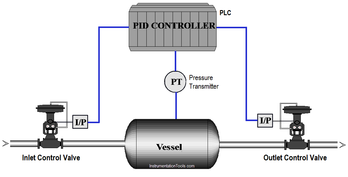
In chemical industry, chemical reactants were made using different vessels, in such applications sometimes we have to control the inlet flow and outlet flow based on pressure inside the vessel.

The inlet control valve and outlet control valve are used to maintain the vessel flow rates. Write PLC program for this application using ladder diagram language.

Problem Diagram

Opposite Acting Control Valves Application

Problem Solution

For this application, we use opposite control concept. Here we are considered reactor control example.

We have two control valves, inlet valve is used for chemical reactants control and output control valve is used for flow control.

Pressure transmitter is used for pressure measurement in the reactor/vessel. If the pressure is too low in the reactor, controller will open the inlet valve.

Assume Inlet valve is fully closed and outlet valve is fully open when controller output is 0% (opposite acting control). At 50% output of controller, both the valves are 50% open.

If controller output is 100%, inlet valve is fully open and outlet valve is fully closed.

Note : In PLC Logic we use only one PID controller for controlling both Input and Output Control Valves. Generally we use a SPLIT block after the PID controller output in PLC using programming. so we can connect the two control valves with separate analog output of the PLC. Hence you can calculate output range in PLC.

List of Inputs and Outputs

Inputs List

  • Analog input form PT :- IW64

Outputs List

  • Inlet control valve :- QW96
  • Outlet control valve :- QW98

M memory

  • Set pressure :- MD500
  • Actual pressure :- MD704
  • PID output (%) :- MD758
  • PID output (analog) :- MW762
  • PID state word :- MW770
  • PID error word :- MD778
  • PID output for inlet valve :- MD762
  • PID enable input :- M61.0
  • PID manual mode enable input :- M61.1
  • PID controller reset :- M61.2
  • PID high limit alarm :- M766.0
  • PID low limit alarm :- M766.1
  • PID input warning :- M766.2

PLC Ladder Logic for Control Valves

Two Control Valves PLC Logic Two Control Valves PLC Ladder Diagram Two Control Valves PLC Programming

Program Description

For this application, we used S7-300 PLC and TIA portal software for programming.

Network 1:

In the network, we configured standard parameters for PID function.

  • “Drive PID”.sRet.r_Ctrl_Gain:- saved proportional gain or P gain for PID (1.0).
  • “Drive PID”.sRet.r_Ctrl_Ti:-Saved integral time or I gain for PID (20s).

Network 2:

“Drive PID”.sRet.r_Ctrl_Td:-Saved derivative time or D gain for PID (0s).

Network 3:

Here we have taken pressure PID max output limit and minimum output limit. We considered here max limit for PID output 100 and minimum limit is 0.

Network 4:

Sampling time of the PID_Compact instruction r_Cycle is determined automatically and usually equivalent to the cycle time of the calling OB. Consider 0.1s for this application.

Network 5:

When PID enable (M61.0) is pressed PID block will be executed. As per SET point (MD500) it will generate output (0-27648) and according to actual pressure transmitter will give feedback (IW96) to PID.Manual enable (M61.1) is for manual operation and PID reset (M61.2) is for resetting the PID.

Network 6:

Activate Mode after CPU restart If sb_RunModeByStartup = FALSE, the controller will remain inactive after a CPU startup.

Network 7:

Here we calculated the PID output range for the inlet valve (reactants).It will be fully open when PID output reaches 100%.

Network 8:

Here PID output is calculated for outlet valve (Products). When PID output reaches 100% output, outlet valve is fully closed.

Note : Above application may be different from actual application. We can also make this application by using Stand-alone PID controller and current to pressure converters. This example is only for explanation purpose. We can implement this logic in other PLC software also. This is the simple opposite acting control application for the valves used in industry, we can use this concept in other examples also.

All parameters and graphical representations considered in this example are for explanation purpose only, parameters or representation may be different in actual applications. Also all interlocks are not considered in the application.

Author: Bhavesh

If you liked this article, then please subscribe to our YouTube Channel for PLC and SCADA video tutorials.

You can also follow us on Facebook and Twitter to receive daily updates.

Read Next:

  • Automatic Empty Bottle detection
  • PLC Program for Paint Spraying
  • Motor Speed Control using VFD Drive
Don't Miss Our Updates
Be the first to get exclusive content straight to your email.
We promise not to spam you. You can unsubscribe at any time.
Invalid email address
You've successfully subscribed !
Software Redundancy in Siemens PLC – Hardware versus Software
UPS Working Principle and Types – Offline and Online UPS Systems
How PLC Reads the Data from Field Transmitters
Micro PLC Hardware Configuration
PLC Wiring Questions for Technicians and Engineers
Share This Article
Facebook Whatsapp Whatsapp LinkedIn Copy Link
Share
2 Comments
  • Michael Zihumo says:
    January 13, 2022 at 3:00 am

    Tag MD762 is not used on the program and MW762 is assigned two different symbolic names(PID OUTPUT-ANALOG & PID OUTPUTS FOR INLET VALVE)

    Reply
  • Manoj says:
    June 6, 2023 at 3:57 pm

    How to write program for default set point 40% for control valve?

    Reply

Leave a Reply Cancel reply

Your email address will not be published. Required fields are marked *

Stay Connected

128.3kFollowersLike
69.1kFollowersFollow
208kSubscribersSubscribe
38kFollowersFollow

Categories

Recent Comments

  • Guifty Shimica on Top Non-PLC Certification Courses for Automation Professionals
  • Guifty Shimica on Top Non-PLC Certification Courses for Automation Professionals
  • MIHARITSOA Aina Sitraka on Top Non-PLC Certification Courses for Automation Professionals
  • Vaishnavi on Free Instrumentation Course for Trainee Engineers

Related Articles

PLC Program to Count and Pack Parts from conveyor

Count and Pack Objects from Conveyor using PLC Ladder Logic

Relay Permissive and interlock circuits

Basics of Permissive and Interlock Circuits

Safety PLC Programming steps

Safety Door Interlock PLC Program

Marking Machine

PLC SCL Program for Marking Machine

Controlling of Tank Level Using Proportional Controller in PLC

Controlling of Tank Level Using Proportional Controller in PLC

Omron PLC real-time clock street lighting program

Automatic Highway Lights Program using RTC in Omron PLC

Light ON OFF Control using PLC

Light ON OFF Control using PLC

Top Automation Vendors

Top Automation Vendors from Around the World – An Overview

More Articles

PLC Program with 2 Toggle Switches and 4 Motors

PLC Program with 2 Toggle Switches and 4 Motors

Instrumentation and Control Project Packages

Instrumentation and Control Project Packages – Detail Engineering

Peripheral Inputs and Outputs in Siemens PLC

Peripheral Inputs and Outputs in Siemens PLC

Argonite/CO2 Flooding System Master & Slave Cylinder Operation

Industrial Automation and Control Interview Questions

Industrial Automation and Control Interview Questions

PLC Program for Alarm Indication in Process

PLC Program for Alarm Indication in Process Control

Basics of Actuators

Basics of Actuators

Steam Eductor Question

Steam Eductor Question

Follow US
All rights reserved. Reproduction in whole or in part without written permission is prohibited.
Welcome Back!

Sign in to your account

Username or Email Address
Password

Lost your password?