Normally open and normally close contacts are widely used in automation. Various tasks like starting the drive, stopping the drive, knowing the running status of the drive, open and close feedbacks of the valve, level switches, pressure switches, and many more applications make use of normally open and normally close contact.
Many times, some of us get confused and even sometimes make mistakes while using normally open and normally close contact. Today we will understand both of them in a very simple manner.
What are NO and NC contacts?
NO and NC contacts are a part of switches and relays. Some switches and relays have single NO and NC contact, while some have multiple NO and NC contacts.
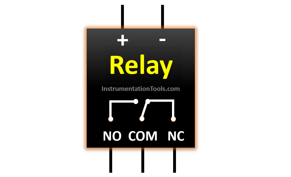
The above figure shows NO (Normally Open), NC (Normally Close), and COM (common) terminals.
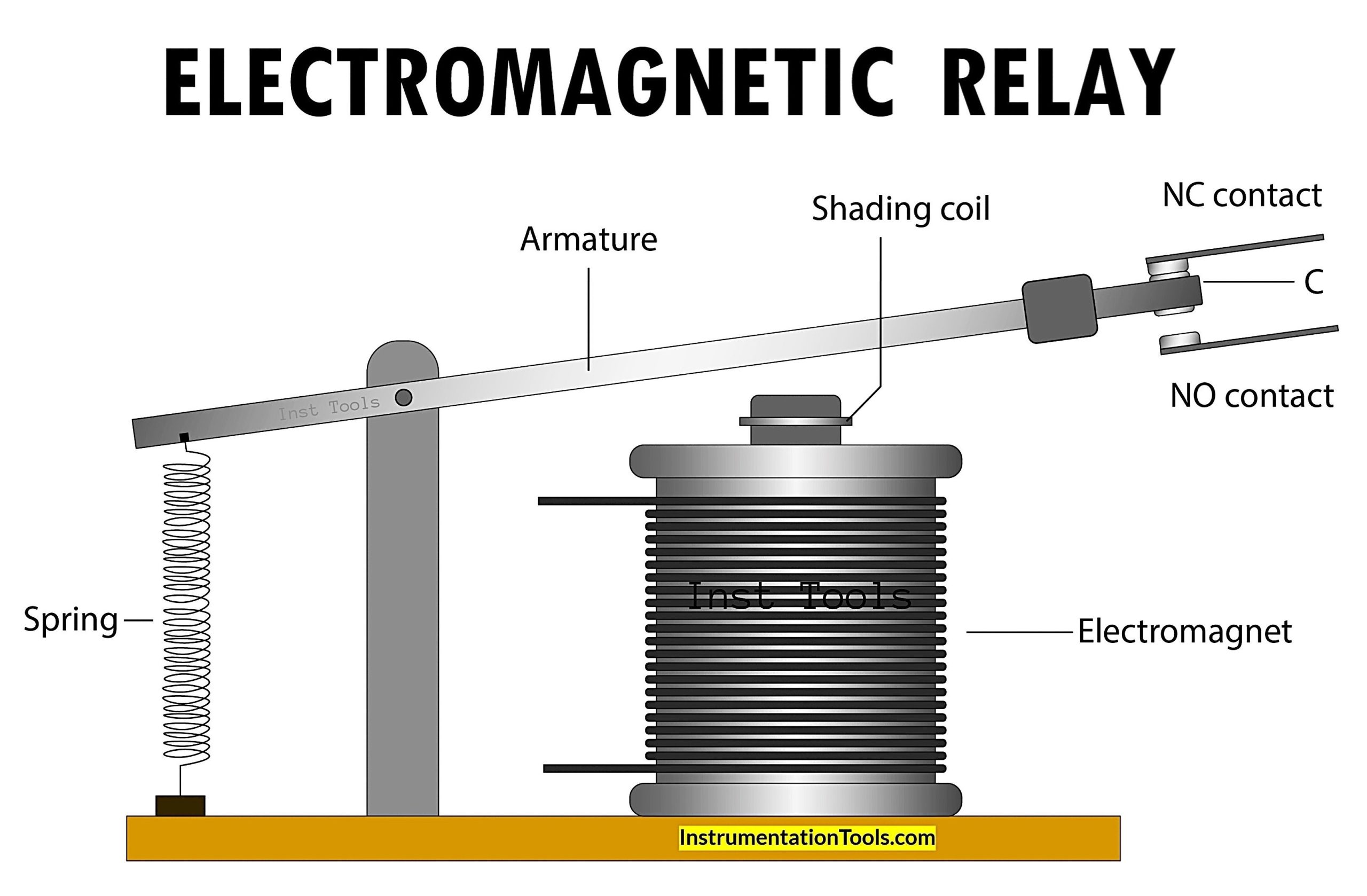
A relay is shown in the above figure. A relay has a positive and negative terminal to energize the relay’s coil when needed. NO (Normally Open), NC (Normally Close), and COM (common) terminals are also shown on the bottom side of the relay.
When the relay is de-energized, NC and COM terminals are connected or say close, and NO and COM terminals are not connected or say open. When the relay energizes upon receiving the appropriate excitation voltage on the coil terminals, the NO and COM terminals get connected or say get closed. At this point, NC and COM terminals are not connected or say get open. Because of this reason, the name of NO and NC contact came as it shows the normal condition of the relay when it is de-energized.
When to use NO contact and when to use NC contact?
Selecting NO and NC contacts while doing connections or designing plays a very crucial role. This selection can impact the safety of the system.
In simple terms, we can say that whenever safety comes, we need to use NC and COM terminals in a switch. Examples are stop push button contact, low-level switches, and many such applications which are critical and safety comes into the picture. Here, in healthy condition, i.e. when the stop push button is not pressed, when the low-level switch is not in alarm state, the NC and COM terminals will be in connected condition or say close condition. Whenever the stop push button is pressed or the low-level switch is actuated, the contact will become open.
NO and COM terminals are used in non-critical applications like starting a drive, run feedback of the drive, feedback of a valve, and other such applications. In non-actuated conditions, the NO and COM terminals will not be connected, and they will be said to be in open condition. When actuated, the contacts will become connected or say they will become close.
In the case of relays also, when the condition is healthy in critical loops, the contact should be closed and when the relay drops in case of emergency requirement, the contact should become open.
Can we use NO and COM terminals in a switch for a stop push button or a low-level switch? The answer to this question is a big NO. Let us understand this by taking a real-life example.
A real-life example of a blunder caused by the use of incorrect contact
For a drive, a stop push button was given in the field to stop the drive when needed. During the field round, a field operator observed some abnormality in the field and tried to stop the drive manually using the stop push button. But by pressing the stop push button, the drive did not stop. The operator tried multiple times to stop the drive using the stop push button, but he was unsuccessful. So, he contacted the panel engineer to stop the drive.
On checking, it was found that one terminal on the stop push button was disconnected due to which the signal did not get captured by the system as NO and COM terminals were used.
Here, we already discussed that in critical and safety-related applications, NC and COM terminals should be used. The reason is that by using NC and COM terminals, any fault in the loop can also be identified easily. Also, to avoid spurious tripping, we can use 2 contacts and configure them as 2 out of 2 for tripping signals.
A blunder in terminology that almost 60% to 70% of engineers use in terminology that often creates confusion.
We often came across people saying currently NO contact became NC or NC contact became NO. The correct terminology is NO contact becomes close or NC contact becomes open. The contact does not change its type.
NO versus NC
| NO Contact | NC Contact |
| NO contact is open (no current flow) in its normal, unenergized state. | NC contact is closed (current flows) in its normal, unenergized state. |
| NO contact closes the circuit, allowing current to flow when energized. | NC contact opens the circuit, stopping current flow when energized. |
| NO contact remains open, with no current flow, when de-energized. | NO contact is used to start or trigger a process in industrial applications. |
| NO contact is typically used to switch ON devices like lights, motors, or other loads. | NC contact is typically used for safety systems, emergency stops, or interlocks. |
| NO contact is represented with an open line or gap in schematics. | NC contact is represented with a closed line or bridge in schematics. |
| NO contact is used in applications like the start button of a machine or motor. | NC contact is used in applications like emergency stop buttons or safety circuits. |
| NO contact keeps the circuit open under fault conditions, so the load stays OFF. | NC contact keeps the circuit closed under fault conditions, so the load remains powered. |
| NO contact is not fail-safe and does not provide protection on failure. | NC contact is fail-safe and stops the machine in case of failure. |
| NO contact does not allow current to flow in its normal (unenergized) state. | NC contact allows current to flow in its normal (unenergized) state. |
| NO contact in a relay or contactor closes when the relay coil is energized. | NC contact in a relay or contactor opens when the relay coil is energized. |
| NO contact is used for starting or triggering a process in industrial applications. | NC contact is used for stopping a process or ensure safety in industrial applications. |
| NO contact is activated by a push-button or toggle switch for turning ON. | NC contact is deactivated by a push-button or toggle switch for turning OFF. |
Read Next:
- De-energize to Safe Loop Basic Philosophy
- Solenoid Valve’s Energized or De-energized
- Motor Forward and Reverse Direction Control
- Top 300 Electrical Circuits Questions Answers
- Free Electrical Circuit Simulators Download