Without use of insulating material it is impossible to use electrical supply. The insulators are used to separate the conducting and non-conducting parts. The operational reliability of the insulating material is vital for making the electrical system reliable. About 98 % faults are phase to earth faults and it happens because of insulation failures.
Therefore, it is very important to check the insulation resistance value of the insulating materials used for electrical system.
The very simple method to check the insulating material resistance is through measurement of the insulation resistance. The insulation resistance is checked by megger or insulation tester.
The voltage is applied between the live part and the ground part to check the insulation resistance. The insulation resistance of the insulator can be expressed with following mathematical expression.
R = V/I
Where,
R = Insulation Resistance
V = Voltage applied
I = Current passing through insulating material
Sometimes, only checking insulation resistance value using the megger is inadequate, and it does not give the healthiness of the system.
To check the insulating quality, the more advanced tests are carried out to determine the remaining useful life of the insulating material.
The followings tests are performed to check the healthiness of the insulator.
- Polarization Index Test
- Dielectric Absorption Ratio (DAR) or DA Test
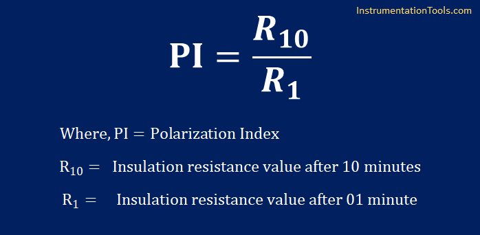
Polarization Index (PI) Test
The polarization Index is nothing but the ratio of insulation resistance after 10 minutes and after 1 minute.
How PI Test is Performed?
In PI test, ratio of insulation resistance at different times after starting of test is recorded.
The DC voltage is applied between conductors and insulating part, and the insulation resistance value is recorded after 1 minute, then test is continued and the insulation resistance value after 10 minutes is recorded.
What should be the PI Value?
The PI value of the insulator must be above 2. The more PI value shows good insulation of the insulating material.
Dielectric Absorption Ratio (DA or DAR) Test
Similar to PI test, it is the ratio test carried out to judge the quality of the insulation.
Dielectric Absorption Ratio (DA or DAR) Test is the ratio of insulation resistance after 60 seconds and 30 seconds.
DAR indicates how quickly the capacitive current becomes zero. The capacitive current in a healthy insulation system must decay within one minute.
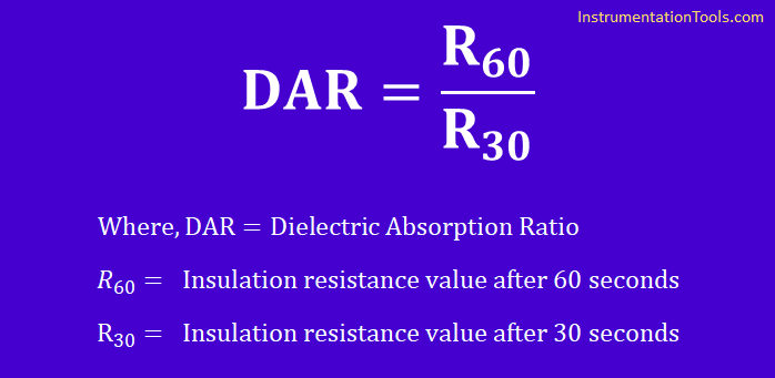
How DAR Test is performed?
In DAR test, ratio of insulation resistance at different times after starting of test is recorded.
The voltage is applied between conducting and insulating part, and the insulation resistance value is recorded after 30 seconds, then test is continued and the insulation resistance value after 60 seconds.
Advantage of PI and DA Test
The insulation resistance decrease with increase in temperature. Thus the measured insulation resistance value may be differ for different temperature.
However, PI and DAR is the IR ratio measurement, therefore the measurement is independent of temperature.
Author: Satyadeo Vyas
If you liked this article, then please subscribe to our YouTube Channel for Instrumentation, Electrical, PLC, and SCADA video tutorials.
You can also follow us on Facebook and Twitter to receive daily updates.
Read Next: