For decades, process instrumentation specifiers have faced the decision whether to use a switch or a transmitter for a given application. Either type of instrument can be used to effectively control industrial processes and protect equipment and personnel – and each has associated pros and cons. Application specifics typically drive decision-making, dictating which approach is most effective from performance, cost and life-cycle support perspectives.
At its most basic, a switch acts in a binary fashion, changing state when a pressure, temperature, level or other process variable crosses over some predefined threshold. If the process variable in question can be allowed to vary in the course of normal operation, a simple switch linked to an on/off valve or pump can effectively and reliably control the process at hand, keeping a tank from running dry or a temperature from climbing too high.
Even now, in order to control a relatively simple process, to reduce the cost of construction, the switch or switches are still widely used.
Switch referred to are:
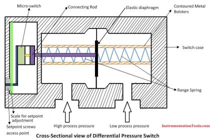
- Pressure switch
- Level switch
- Temperature switch
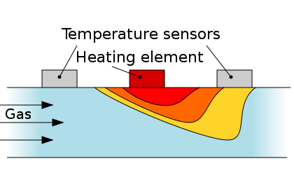
- Flow switches
- Vibration switch
- Limit switch
- Etc.
The question is, on alarm and shutdown systems, whether it should be installed NO (normally open) or NC (normally closed)?
NO and NC is naming the condition or state of the switch when the switch is not installed or not in-service or no action of the parameters it detects.
In addition to NO and NC there is another term for the world’s per-switch, NE (Normally Energize) and ND (Normally De-energize) is another term for it. NE is a state of switches that close when it detects parameters are in normal state, the switch will open if the parameter detects an abnormal (low or high pressure, for example). While ND is the state of switches that open when it detects parameters are in normal state, the switch will close if the parameter detects an abnormal (low or high pressure, for example).
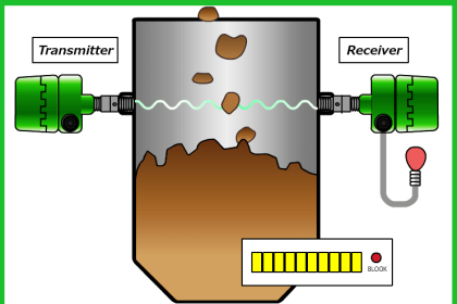
Consider the following picture:
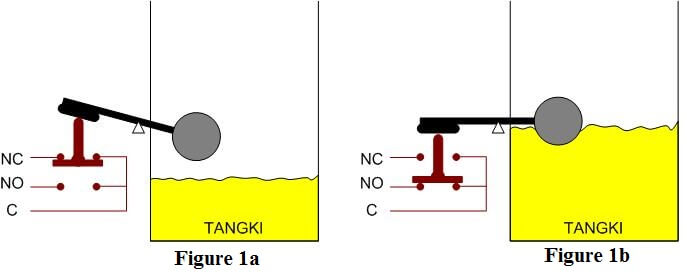
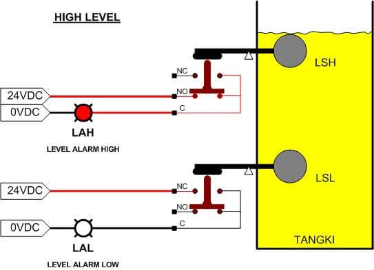
In Figure 1, an LS (level switch) installed to detect the liquid level inside a tank. LS is for example used to detect a high level (LSH = Level Switch High).
Figure 1a shows the level in a normal state or in a state of high. Common terminal (C) will be connected to the NC terminal, or C-NC in a state energize, and C-NO in a state de-energize.
Figure 1b shows the level in a normal state or in a state of high. Common terminal (C) will be connected to the NO terminal, or C-NO in a state energize, and the C-NC in a state de-energize.
Let us take an example, the application-level switch for detecting low level (LSL = Level Switch Low)and high level (LSH = Level Switch High). Samples taken in order to facilitate the visualization level, because we can facilitate the “level” compared with the “pressure”, because visually directly, we never could see the pressure, just believe in the pressure gauge or pressure indicator.
For example we will use a level switch for detecting low level (LSL) and a level other switches to detect thehigh level (LSH), as shown below.
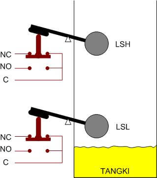
For example the two switches are connected with an indicator light to indicate each low level and high level, for example, if the normal level of the indicator light to be extinguished, and if low or high levels ofthe respective indicator light should be on.
The question is, which contacts should be used for LSL, whether NO or NC. Similarly to LSH, whether NO or NC?
OK, let’s say we are to the point, let’s say we only focus on the logic that, if low level, the indicator must be lit, if a high level, the indicator light should also light up. So, without any consideration, only consideration of logic alone, approximately its wiring diagram will be as follows:
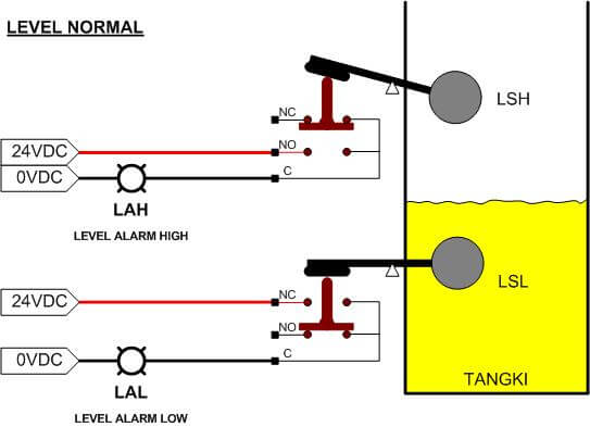
Referring to the picture above, the level is in the normal state, LSL using the contact C-NC, and the normal time, the contact becomes deenergize, while LSH using the contact C-NO, and the normal time, the contact becomes deenergize well.
Normal times, the electric current does not make the indicator light LAL, because interrupted by LSL who are deenergize. As well as with LAH, electric current does not make the indicator light LAH because interrupted by LSH, so the indicator goes out, indicating the level in normal circumstances.
What if there is a low level? Note the picture below:
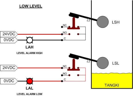
Ignore LAH, because it has not changed. Now we observe LAL. Due to the low level, LSL who use contact C-NC, which was deenergize be energize so that electric current into the LAL indicator lights, and the lights lit indikatorpun indicates that there was a low level.
How did the case of a high level? Note the picture below:
Ignore LAL, because it has not changed. Now we observe LAH. Due to the high level, LSH which uses C-NO contacts, which had deenergize be energize so that electric current into the LAL indicator lights, and the lights lit indikatorpun indicates that there was a low level.
Requirements logic as described above, that:
“If the normal level of the indicator light to be extinguished, and if low or high levels of the respective indicator light should be on.”
Does the selection NO / NC on the wiring diagram that we created earlier to meet the requirements of thelogic? Please answer ….
What if one of the switches wired connection is disconnected due to one reason or another? Is the level of the indicator still able to function? Well, to further facilitate the earlier analogy, look at the picture below:
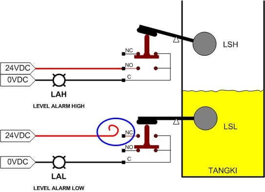
Voltage source such as a cable that goes to LSL (terminal NC) is lost (as in the picture circled in blue), and going on a low level. Are LAL can still light up to indicate that there was a low level?
In logic, wiring above has fulfilled its function, ie if a normal level, the indicator light goes out, and vice versa in case of abnormal (low level or high level), the respective indicator lights will illuminate indicating that the level was not normal.
In the example picture above, if the level in a normal state, the indicator light goes out, then for one reason or another, all of a sudden one of the cable disconnected, and then going on a low level. What will happen? Yes … the indicators will remain extinguished, and the operator will not know if the level in the tank is undergoing a state of low-level. This is what is meant by not fail-safe. If a system failure (fail), then the system does not exist in a state that is safe (safe).
Please change the switch configuration using a NO (normally energize when the normal level).And change the logic for the lights: If the normal level, lights on, if the low level, the lights went out. Or with the help of a relay, logic can be inverted so that the initial logic can be achieved: If the level is normal, the indicator light goes out, and if the low level, the indicator lights. Once converted, please compare the condition, in case of a cable break one of the LSL. If you wish, write in the “comment” the results of your analysis.
With this understanding, God willing, we will understand the concept of fail-safe for the context of this switch.
In the already complex system with high standards of safety, wiring for the switch is no longer as simple as the above example. Especially that already involves PLC / DCS as its logic solver.Not just any process conditions (in this example is level) monitored / detected, but the state of the wiring detected, whether the open – circuit or short circuit does occur on its wiring.So that the whole system becomes much more reliable.
And mostly, a configuration that is widely used is NO, while “messing around” his logic performed in the logic solver (PLC or DCS).
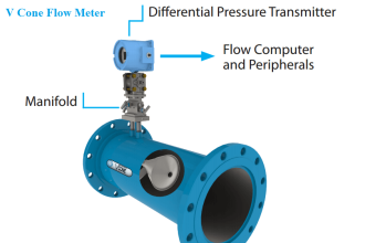
Also Read : Flow Switch Working Principle


pls explain dead band
Appreciated …. but please explain the meaning of the word “Wiring nyapun” used in the 4th last sentence.
Waiting for your response.
Thanks
Noted. Will be updated. Thanks
I appreciate, good work, thank’s a lot sir
Sir, pls explain significance of Low level switches & High level switches.