Inst ToolsInst ToolsInst Tools
  • Courses
  • Automation
    • PLC
    • Control System
    • Safety System
    • Communication
    • Fire & Gas System
  • Instrumentation
    • Design
    • Pressure
    • Temperature
    • Flow
    • Level
    • Vibration
    • Analyzer
    • Control Valve
    • Switch
    • Calibration
    • Erection & Commissioning
  • Interview
    • Instrumentation
    • Electrical
    • Electronics
    • Practical
  • Q&A
    • Instrumentation
    • Control System
    • Electrical
    • Electronics
    • Analog Electronics
    • Digital Electronics
    • Power Electronics
    • Microprocessor
  • Request
Search
  • Books
  • Software
  • Projects
  • Process
  • Tools
  • Basics
  • Formula
  • Power Plant
  • Root Cause Analysis
  • Electrical Basics
  • Animation
  • Standards
  • 4-20 mA Course
  • Siemens PLC Course
Reading: How to Test a Transistor using Multimeter
Share
Notification Show More
Font ResizerAa
Inst ToolsInst Tools
Font ResizerAa
  • Courses
  • Design
  • PLC
  • Interview
  • Control System
Search
  • Courses
  • Automation
    • PLC
    • Control System
    • Safety System
    • Communication
    • Fire & Gas System
  • Instrumentation
    • Design
    • Pressure
    • Temperature
    • Flow
    • Level
    • Vibration
    • Analyzer
    • Control Valve
    • Switch
    • Calibration
    • Erection & Commissioning
  • Interview
    • Instrumentation
    • Electrical
    • Electronics
    • Practical
  • Q&A
    • Instrumentation
    • Control System
    • Electrical
    • Electronics
    • Analog Electronics
    • Digital Electronics
    • Power Electronics
    • Microprocessor
  • Request
Follow US
All rights reserved. Reproduction in whole or in part without written permission is prohibited.
Inst Tools > Blog > Electronic Basics > How to Test a Transistor using Multimeter

How to Test a Transistor using Multimeter

Last updated: May 23, 2017 11:27 am
Editorial Staff
Electronic Basics
No Comments
Share
1 Min Read
SHARE

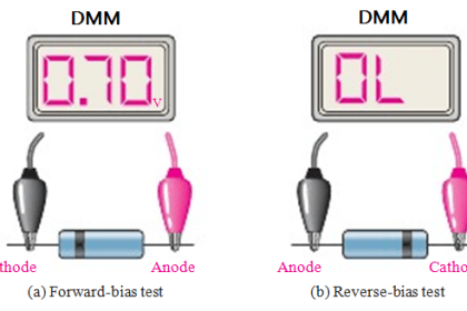
An ohmmeter can be used to check the state of a transistor i.e., whether the transistor is good or not. We know that base-emitter junction of a transistor is forward biased while collector-base junction is reverse biased. Therefore, forward biased base-emitter junction should have low resistance and reverse biased collector-base junction should register a much higher resistance. Fig shows the process of testing an npn transistor with an ohmmeter.

(i) The forward biased base-emitter junction (biased by internal supply) should read a low resistance, typically 100 to 1 k as shown in Fig. (i). If that is so, the transistor is good. However, if it fails this check, the transistor is faulty and it must be replaced.

How to Test a Transistor using Multimeter

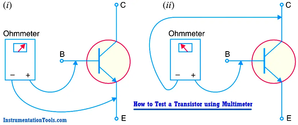
(ii) The reverse biased collector-base junction (again reverse biased by internal supply) should be checked as shown in Fig. (ii). If the reading of the ohmmeter is 100 k  or higher, the transistor is good. If the ohmmeter registers a small resistance, the transistor is faulty and requires replacement.

Note. When testing a pnp transistor, the ohmmeter leads must be reversed. The results of the tests, however, will be the same.

Don't Miss Our Updates
Be the first to get exclusive content straight to your email.
We promise not to spam you. You can unsubscribe at any time.
Invalid email address
You've successfully subscribed !

Continue Reading

How to Measure capacitance using Multimeter
Things to Know When Measuring Current
What is PCB Corrosion? Electronic Boards Corrosion Prevention
What is Cathode Ray oscilloscope ?
Difference Between LED and LDR
What are Analog and Digital Signals? Differences, Examples
Share This Article
Facebook Whatsapp Whatsapp LinkedIn Copy Link
Share
Leave a Comment

Leave a Reply Cancel reply

Your email address will not be published. Required fields are marked *

Stay Connected

128.3kFollowersLike
69.1kFollowersFollow
210kSubscribersSubscribe
38kFollowersFollow

Categories

Explore More

How to Identify the Transistor Terminals
How to Test a Diode using Multimeter
How does SMPS Works? – Switched Mode Power Supply
How are Silicon Chips Disposed?
How to Measure Duty Cycle using Multimeter
Testing a Transistor with a Digital Multimeter
100 Electronics and Electrical Projects for Engineering Students
What is an Electrical Wire Mesh?

Keep Learning

Difference Between LDR and Photodiode

Difference Between LDR and Photodiode

resistor-color-coding-example

IEC labelling for Resistors Color Code

Voltage Regulator Circuit

Basics of Voltage Regulator

Top 100 555 Timer Projects for Engineering Students

Top 555 Timer Projects for Engineering Students

Tank car bonding at siding

Electrical Static Grounding Techniques

How to Test a Battery using Multimeter

How to Test a Battery using a Multimeter?

Zener Diode Regulator

Zener Diode Voltage Regulators

Measure AC Voltage using Multimeter

How to Measure AC Voltage using Multimeter

Learn More

Power Electronics Objective Questions

Single Phase Voltage Source Inverter MCQ

Electrical Machines Objective Questions

Electrical Machines MCQ Series 17

PLC Program using Counters

PLC Counters Program

Grounding Electronic Equipment

Importance of Grounding Electronic Equipment

Encode and Decode Instructions

How to Use Encode and Decode Instructions in PLC ?

Basic Configuration of Motor Operated Valve

Rotork Motor Operated Valve Basic Configuration

Schottky Diode Vs PN junction Diode

Difference between Schottky Diode and PN junction Diode

Test and Electrical Measurement Objective Questions and Answers

100 Test and Electrical Measurement Objective Questions and Answers

Menu

  • About
  • Privacy Policy
  • Copyright

Quick Links

  • Learn PLC
  • Helping Hand
  • Part Time Job

YouTube Subscribe

Follow US
All rights reserved. Reproduction in whole or in part without written permission is prohibited.
Welcome Back!

Sign in to your account

Username or Email Address
Password

Lost your password?