Different types of Motors and Electrical Consumers/ Actuators are used in each Process Plant which shall be controlled by suitable Signal Interfaces based on considered functions in Process Control Philosophy. We try to investigate some of the main Motor Control Signal Interfaces in this article.
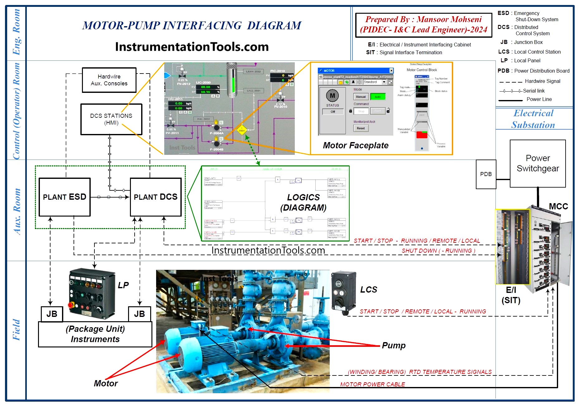
Figure-1: Control Block Diagram for Motor-Pump Signal Interfaces.
Control Block Diagram of Motor-pump Signal Interfaces
Figure 1 shows one sample of a Control Block Diagram (or Interfacing Diagram) for typical Motor-Pump Signal Interfaces that can be considered as the basis of our study. Based on this diagram, we may consider the main process plant locations as:
Field: Location of installation of process equipment, motors, instruments, and all required devices and items for founding Process Plant.
Auxiliary Room (in Control Building): Location of installing all systems (DCS/ESD/PLC/…) cabinets and marshalling panels.
Control (Operator) Room: Location of installing Operator Consoles or workstations.
MCC Room: Location of installing all required Motor Control Circuits including power feeders (MCC Room may be part of Electrical Substations).
It shall be noticed that Figure 1 shows just one sample diagram of Motor-Pump signal interfacings, but however, all other controls of motors (other than pump applications) can be investigated approximately by similar diagram formats with shown (defined) locations.
Further to the defined locations in Figure 1, some equipment, facilities, or positions are to be defined for our study too, as below:
DCS: Distributed/ Digital Control System which is used as a Basic Process Control System (BPCS) for controlling and monitoring the whole Process Plant.
ESD: Emergency Shutdown System which is used as a Safety Instrumented System (SIS) for the protection of the whole Process Plant.
PLC: Programmable Logic Controller which is used as a system for controlling, monitoring, or even protection of a set of equipment in process units or packages.
LCS: Local Control Station, is the facility located near the motor position for controlling the motor (Start/ Stop …) that will be connected to MCC circuits by cable connections.
LP: Local Panel, is the facility located near the motor position for controlling or monitoring some actions related to the motor (Start/ Stop, Commands to Motor Upstream/ Downstream equipment, Indications/ Alarms Lamps, …) that will be connected to the Control and Safety Systems (DCS/ ESD/ PLC …) by cable connections.
SIT or E/I Cabinets: Signal Interface Termination or Electrical/ Instrument Cabinets or Panels are the facilities located near (inside or behind) the MCC Room for transferring signals between MCC circuits and Control and Safety Systems (DCS/ ESD/ PLC …). For more study on this subject, you may refer to the article “Motor Control Center (MCC) Signal Interface Termination (SIT)”.
Terminal Box: Usually refers to the boxes on the motor (or equipment/ instrument) for making hardwire connections with cables (or wires). Some motors (or equipment/instruments) may have more than one terminal box (as an example one for high power/ voltage and the other for low power/ voltage or signal cable connections).
JB: Junction Box is the facility for connecting one or several (Instruments/ Signals) cables to one main cable, which transfers the merged items to the destination point (usually DCS/ ESD/ PLC…).
HMI: Human Machine Interface is the interface facility between the operator (man or human) and system (machine) for transferring signals (commands, acknowledges and alarms). Such facilities may be accomplished by computer workstations, special monitors/ displays, or by hardwired consoles.
Faceplates: Faceplates are special dedicated graphical blocks for grouping the software signals (commands and acknowledges) relevant to one equipment or device (here motor in our study).
Singular Motors or Group of Motors
In Process Plants, motors may be used as singular (each one separately for dedicated function) or as a group of (same function) motors. Usually, when the motors are considered as a group (of the same function), their tag numbers are the same with additional suffixes for counting different motors in the group (See Figure 2).
Although a group of motors may have some interlock (functions) dependencies with each other, usually such interlock (functions) dependencies will be done in the Logic Solver of Control System (rarely for simple package controls such interlocks may be considered in MCC Circuit). However, regardless of whether using motors as singular or group of the same function, each motor will have a dedicated MCC Circuit.
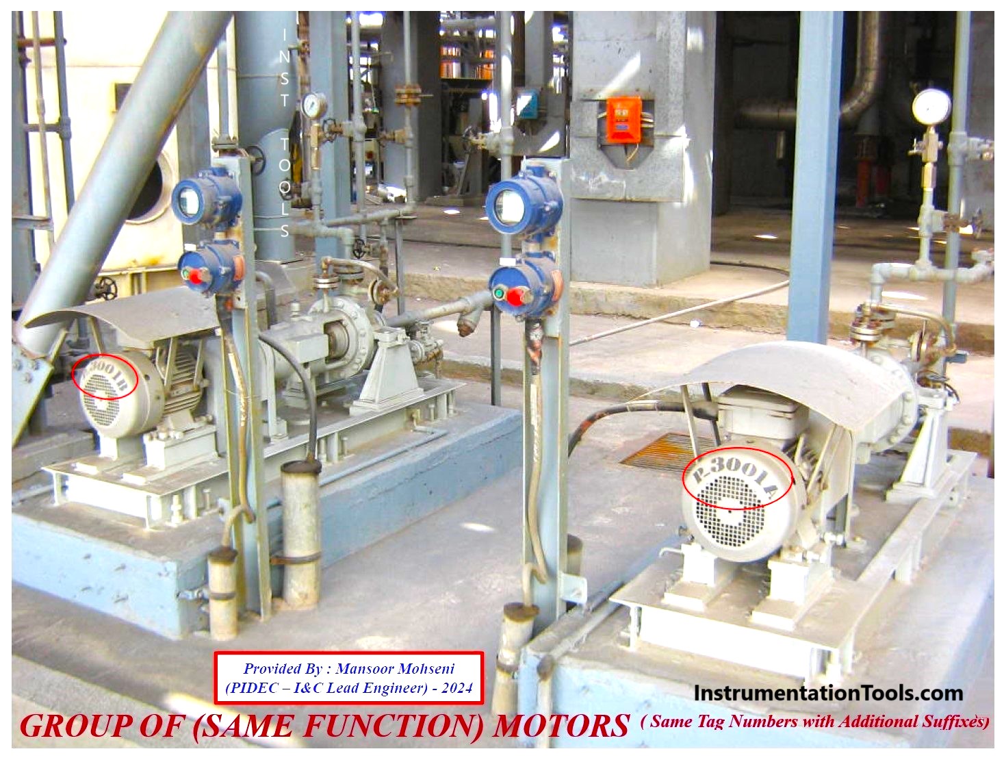
Figure 2: Motors in the Process Plant may be used as a Group of (same function) Motors.
Also if motors are used in packages, the MCC Circuits may be considered inside the Package Vendor’s Scope of supply or may be considered as part of the Process Plant MCC Room. The motors outside packages usually use Process Plant MCC Room for control/ safety functions and signal interfacings.
MCC Circuit
The MCC Circuit of each motor usually has two main parts: the Control Circuit for combining all control and safety functions/logic in the electrical circuit, and the Power Circuit for transferring the electrical power to the motor (and its auxiliary items).
Figure 3 shows a sample of a simple MCC Circuit Diagram for (one typical) motor.
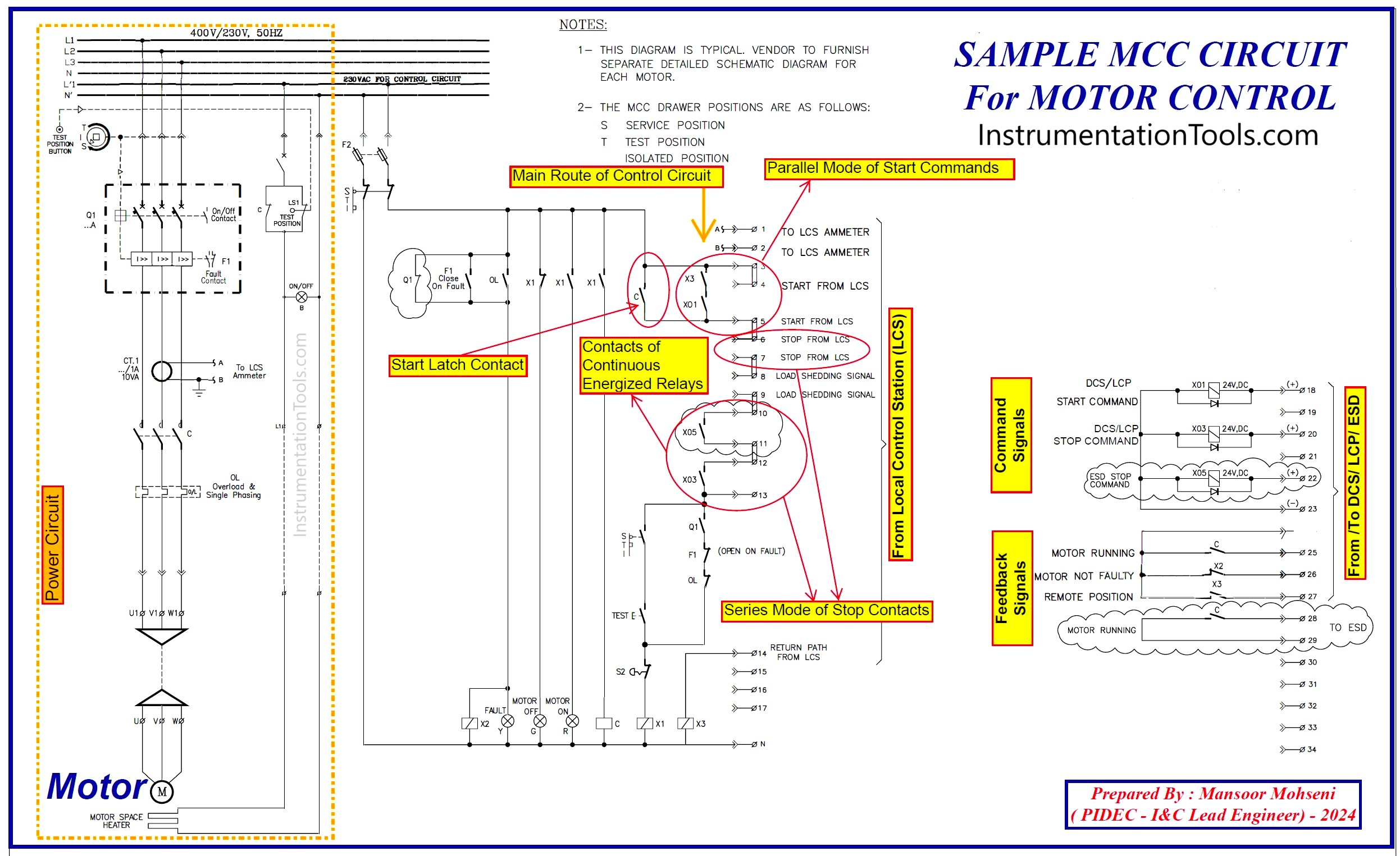
Figure 3: Sample MCC Circuit Diagram for (one typical) Motor.
The other types of Motor Control circuits have a similar format of diagrams like Figure 3, but due to the type and size of the motor and required functionalities, the complexity of the shown circuit will vary.
In Each Process Plant Project, usually, some limited types of MCC Circuit Diagrams (like Figure 3) are used as templates for defining and implementing required control circuits for each motor inside the project. Such considerations will make uniform circuit diagrams and hence easy troubleshooting procedures, and also uniformity in electrical components and hence easiness for replacing each MCC circuit (or cell) or repairing it with less (uniform) spare parts on components.
Motor Control Signals
For preparing MCC Circuit Diagrams like Figure-3, some rules or procedures usually to be considered in mind, some of them will be mentioned here:
- All Stop Commands (Signals) are considered as series contacts in the main route of the Control Circuit.
- All Start Commands (Signals) with relevant conditions are considered as parallel paths (with each other’s) in the main route of the Control Circuit.
- Stop Command signal is Normally Closed Contact and will be opened on Stop Request, while Start Command is Normally Open Contact and will be closed on Start request.
- Motor Run/ Stop Indication is Normally Open Contact (for Stopped) and will be closed on Running Status.
- MCC Fault/ Healthy Indication is Normally Closed Contact (for Healthy) and will be open on Fault Status. It is very important to notice that the Fault signal of the MCC Circuit is not necessarily equal to Motor’s Stopped state. It means that some Fault conditions may stop the motor while some of them may be existed while the motor can continue the run state. Transferring the Fault state to operators may cause immediate actions for troubleshooting the Motor circuit (mainly the motor itself), especially for those faults that motor is not stopped.
- Motor Remote / Local Indication is Normally Open Contact (for Local) and will be closed on the Remote Mode selected.
- MCC Circuit shall have a facility for complete Isolation from the main Power Feeder further to circuit protection (overcurrent) like fuses.
- Motor Winding/ Bearing RTD Protection is connected to MCC (for use in any possible trip or alarm functions)
- It is very important to notice that, the state of relay contacts in the diagram will be shown as normally De-energized condition of relay. By considering this rule, and referring to Figure-3 again, we can find that why Stop Contact of relay for systems stop command was shown as normally open. In fact, the source of stop command (in DCS/ESD/PLC Systems) will be (inherently) normally closed and opens in stop request, and so the relevant rely will be (normally) energized (and relevant normal open contacts will be closed) and will be de-energized on the case of Stop Request Command (and the relevant normally open contacts will be returned to normally open state).
- Also from Figure-3 we can find that the auxiliary contact of the main contactor will have the start latch function role. On the other hand, by using such latch contact, the start command (contact) can be pulse form (instead of permanent function contact).
- Using parallel branches for start command contacts will enable the MCC circuit to start the motor from different locations. For applying any start condition on dedicated command, the relevant (condition) contact shall be located in series with start contact (at that parallel branch).
- Series connection of stop command contacts (in the main route) will enable the MCC circuit from different locations for stopping the motor even by pulse format.
- It is very important to notice that when we use the stop command as pulse format, it is necessary to consider the start commands as pulse type too, since otherwise (in the case of continuous start command) after elapsing stop pulse duration, the Motor control circuit immediately returns to start condition. Please notice that usually start command from Systems (DCS/ESD/PLC) outputs may be pulse type, while the stop command on LCS is the permanent type (switch) contact.
- Generally stop command is defined as a pulse type format while a trip or shutdown command is a permanent type. In fact, in the case of trip conditions since the main route will be opened while the opening state of trip contact, the motor cannot start even from the local control station (LCS), while by using the stop pulse command (and accordingly probable start command with pulse format) from the systems (DCS/ESD/PLC) the motor can be started locally after elapsing pulse duration. In fact, activation of trip commands means the conditions that the motor cannot be started even at the local position.
- It shall be mentioned that in some industrial projects (especially when all commands are combined and transferred to MCC from outside the circuit (and probably inside the systems logic) start and stop commands are merged together and they are completely in opposite states of each other and so the whole circuit will operate right with just one command signal (“1” for start and “0” for stop).
- Start and stop commands from systems (DCS/ESD/PLC) will be transferred to the MCC Circuit via (usually 24 VDC) isolation relays. Such relays in Figure-3 are shown as located in the MCC circuit, but in some industrial projects, they may be located in SIT or E/I cabinets or panels. Also in some industrial projects for transferring feedback signals additional (24VDC) isolation relays may be used too.
- As Figure-3 shows some specified terminal connections are considered for signal interfacing with LCS and DCS/ ESD/ PLC. If such terminal connections are designed in such a way that all diagrams (templates) have the same terminal numbers, such interface connections will be standard and so the troubleshooting and maintenance and repair will be done more easily (for all MCC circuit types).
Complex MCC Circuits
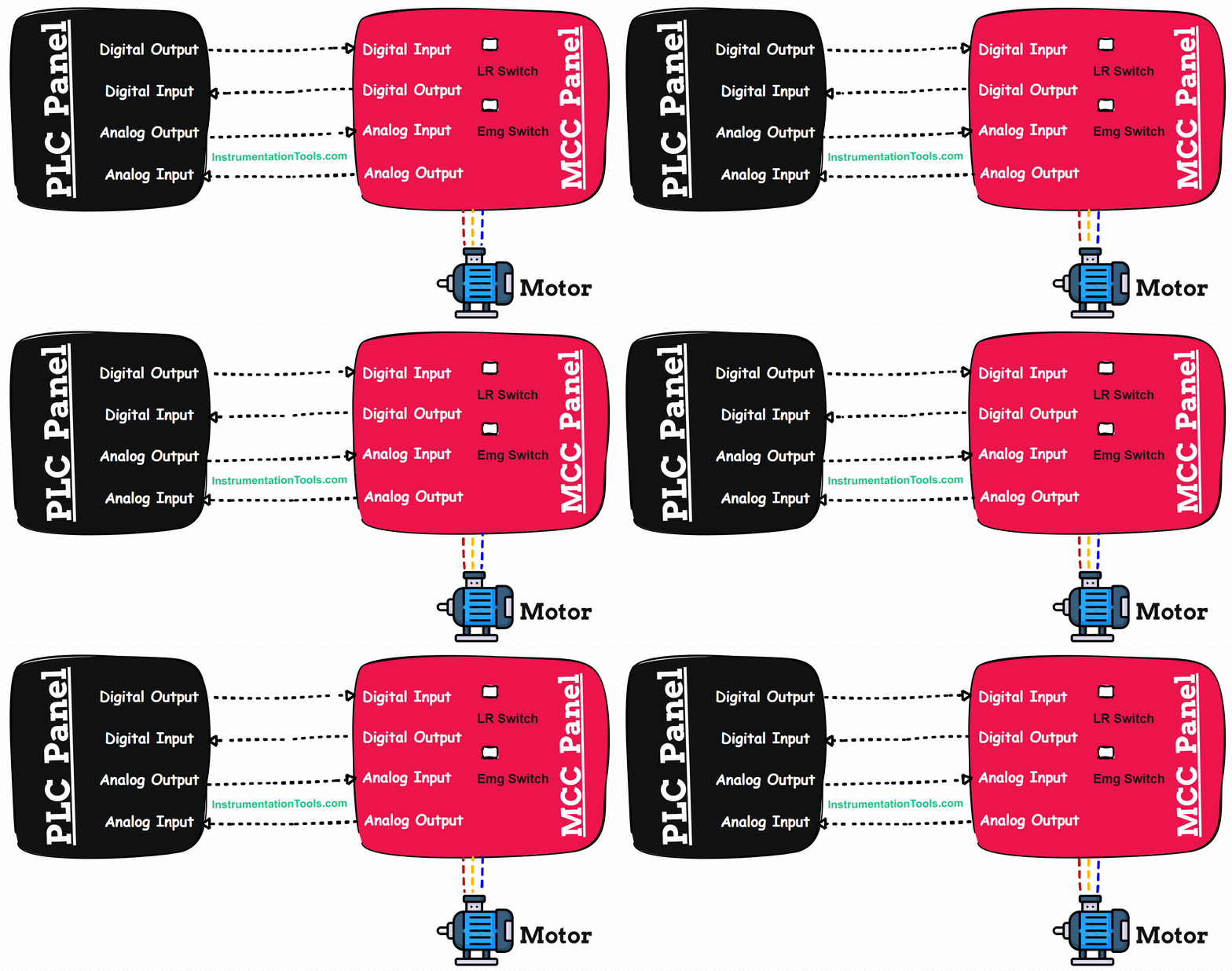
As mentioned above, Figure-3 is shown just a simple MCC Circuit Diagram, while for big motors or complex functionalities, such a circuit may be more complex. Since the complexity of the circuit depends on each considered case, and so the configurations of the circuits may vary differently, we mentioned here just some of the applicable conditions that may be considered in usual common complex cases.
- Providing Motor Current feedback to DCS/ UCP as an Analog Signal.
- Using Forward / Reverse Functionality of Motor, Jogging Facility…
- Using Variable Speed Drive (VSD / VFD) for Motor Speed Control.
- Receiving Analog Input from DCS/UCP for Speed Set-point and having Analog Outputs for Speed Feedback to DCS/UCP.
- Using Ready To Start and Start Permit Signals in Motor Starting Sequence.
- Using Two Speeds Motor applications.
- Providing additional information to the operator as Analog/ Digital Signals on feedbacks like Motor Power, Torque, Temperature, Vibration, etc.
Local Control Station (LCS)
As defined above LCS is the facility for controlling the Motor at the field while required actions are provided by MCC Circuit.
For the LCS application, we may consider some below items:
- Defining some applicable LCS for different Motors and applicable actions or functions to that motor. Figure-4 shows some examples of typical LCS configurations and considered relevant components and circuit facilities.
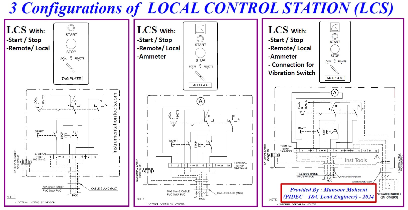
Figure 4: Some examples of typical LCS configurations and considered relevant components and circuit facilities.
- In the case of the Ammeter required, it can be part of LCS (/LP) or it can be connected to LCS (/LP). If an Ammeter is installed outside the LCS, the variety of types of LCS will be less. Figures 5 and 6 show two applicable cases for LCS (including Ammeter, and considering Ammeter outside the LCS).
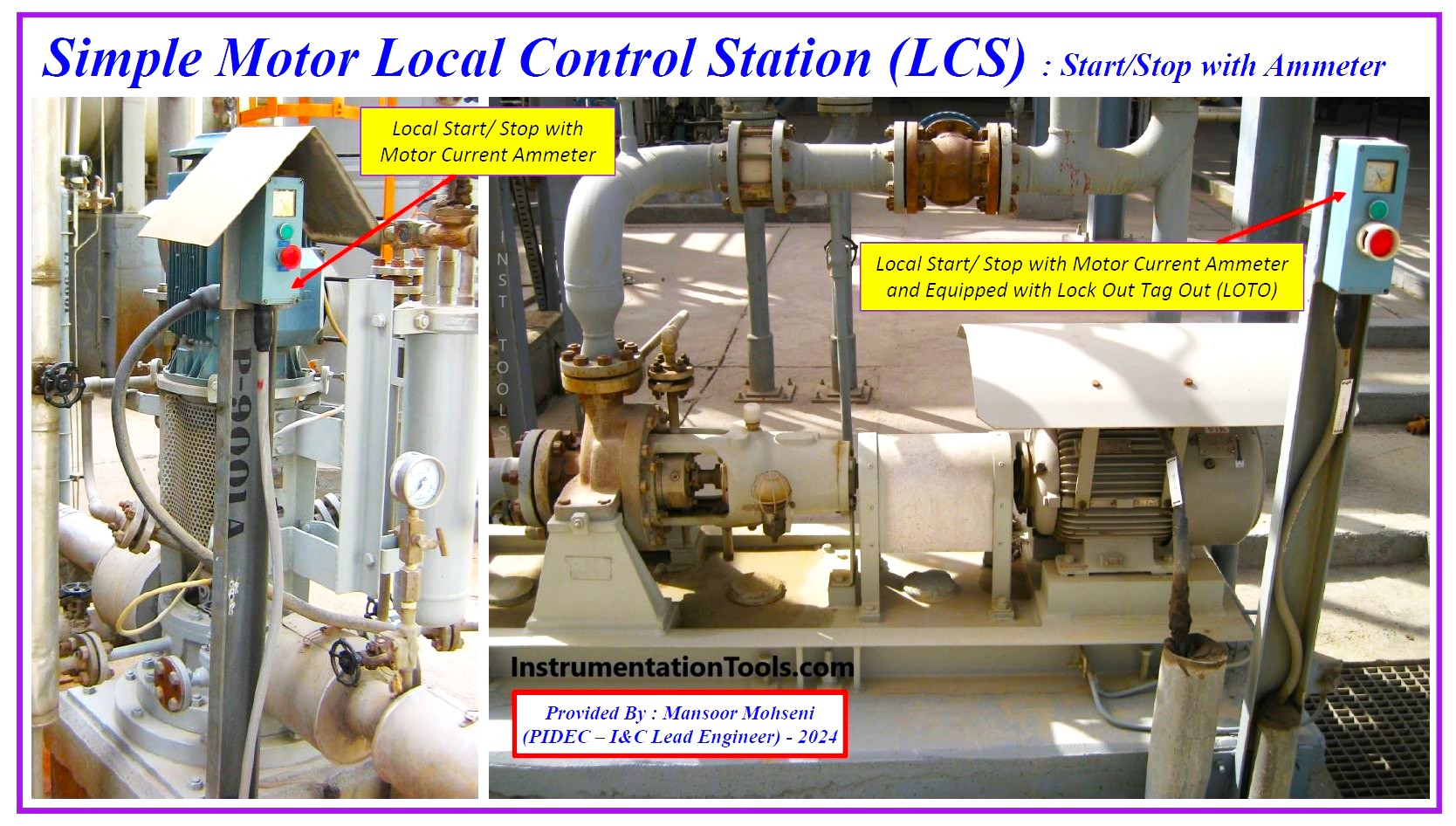
Figure 5: Examples of LCSs equipped with an Ammeter for Motor current indication.
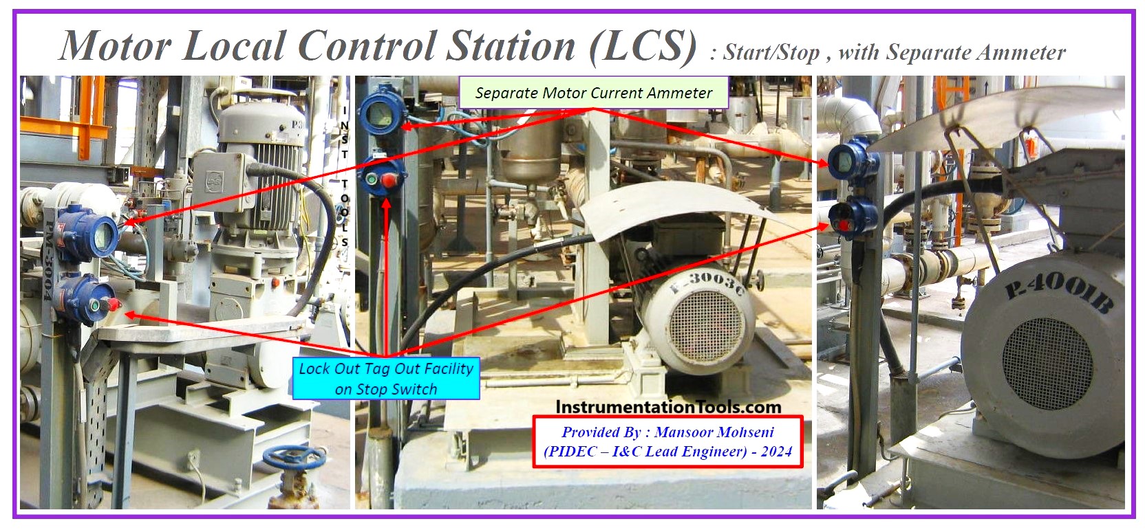
Figure 6: Examples of LCSs using separate Ammeter (outside the LCS) for Motor current indication.
- Using Explosion/ Hazardous Protection type of LCS for Hazardous Areas.
- If the status of Motor Running is important for operators far away, the LCS shall be equipped with a motor Run Indication Lamp. The lamp facility may be considered as part of (start) switches or may be installed separately.
- Transferring some protection signal (like a Vibration Switch) to the MCC Circuit (for some limited cases).
Local Control Stations may appear in different shapes or formats (and sizes) in industrial projects (depending on project requirements and vendor products), but their configurations (functionalities) are mainly the same. (See Figure-7)
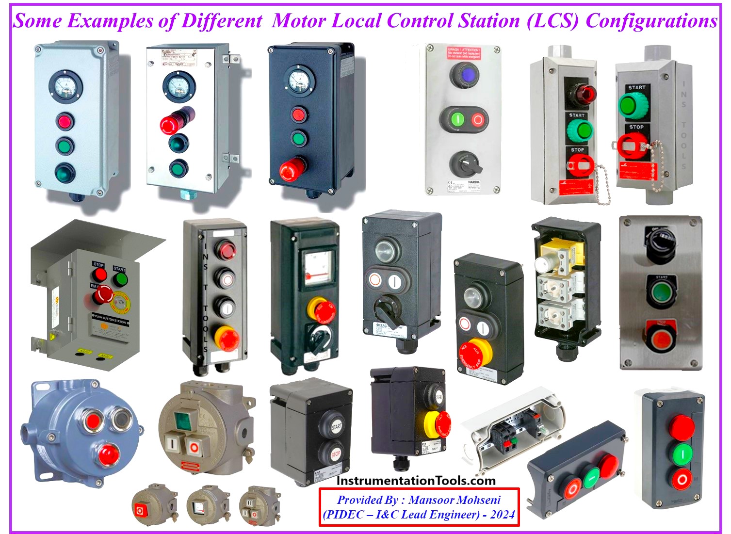
Figure 7: Some Examples of Different Configurations with different facilities/ shapes/ sizes/ specifications (as an example Hazardous Area Protection).
Field (Maintenance/ Operation) Facilities
As mentioned, Local Control Stations (LCS) are used as Field (Maintenance/ Operation) facilities, but further to LCS some other items to be considered for such subjects.
Some of them are mentioned here:
- Lock Out / Tag Out (LOTO) facility to be considered at Local field place ( on LCS or LP).
- LOTO facility may be considered on the Emergency Stop Button (on LCS or LP) or on the “0” position of the Remote / Local selector switch (see Figures 8 and 9).
- For Motor Cable disconnection, the MCC shall be in Isolated Mode (with suitable warnings in the MCC Room).
- For checking and opening the RTD termination box, exact care is to be done (Motor isolated Mode is recommended).
- Complete coordination and communications between all plant-responsible persons for any maintenance activities. In fact, the Plant Process Operators shall be completely aware of the Motor in maintenance Mode (especially when the Process Plant is in Running Mode).
Figures 8 to 9 show considered LOTO Facilities on LCS while Figure 10 shows LCS without such facilities (poor design).
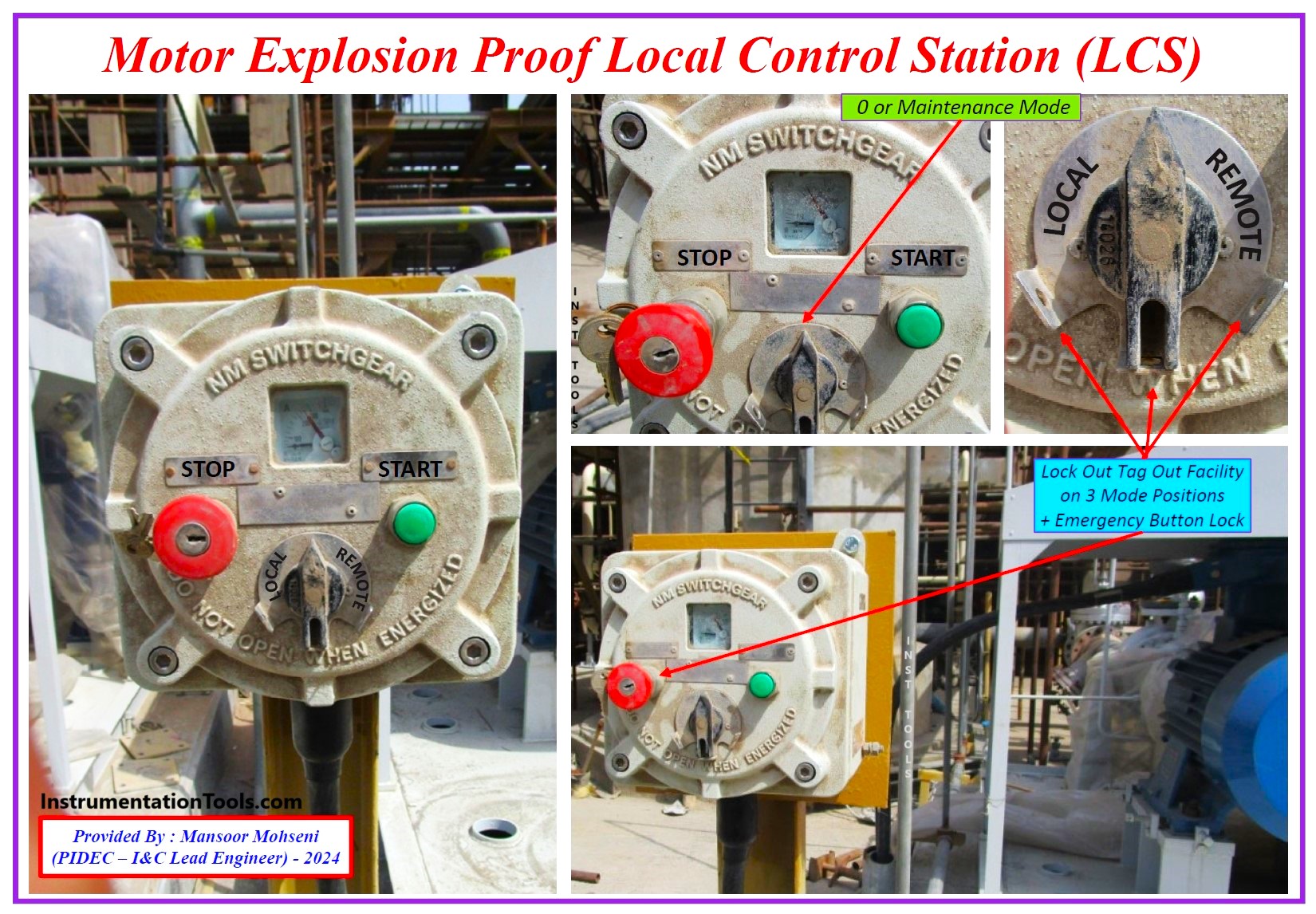
Figure-8: Sample of LCS Configuration equipped with LOTO Facility.
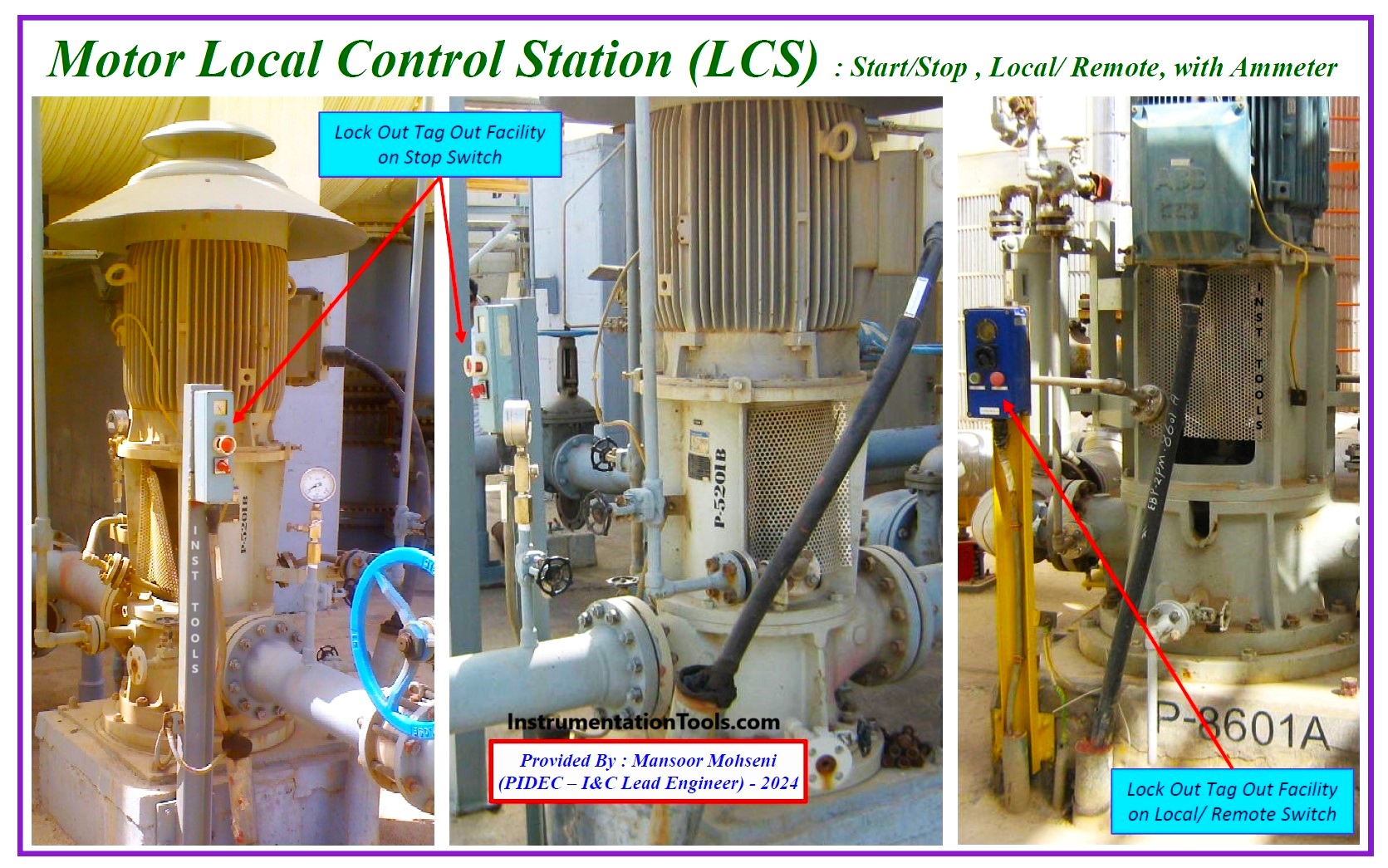
Figure-9: Some applications of LCS Configuration equipped with LOTO Facility.
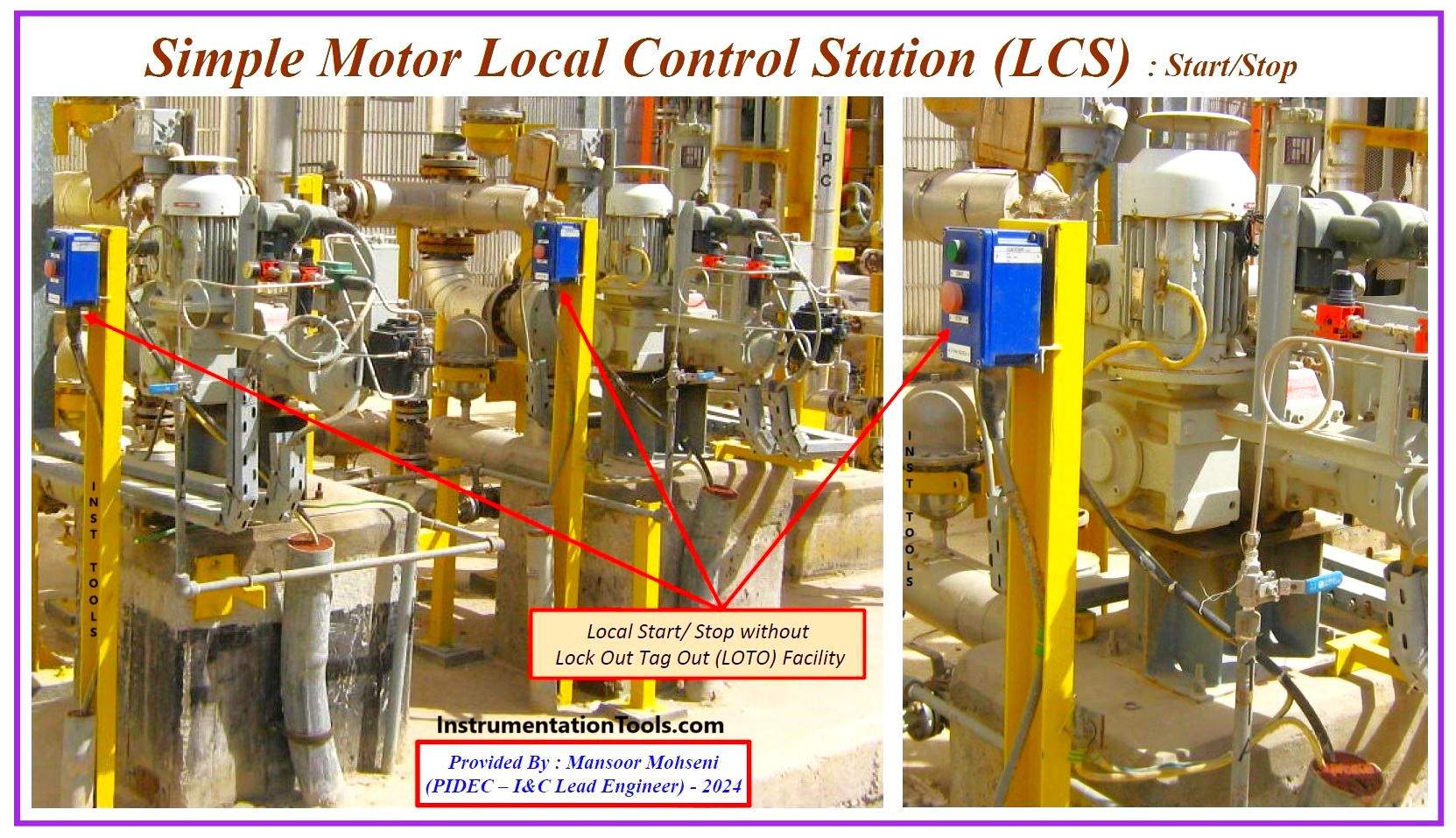
Figure-10: Some applications of LCS Configuration without LOTO Facility (poor design).
BPCS/ DCS Logic Implementation
For controlling the motors of Process Plant Industries, the main signals will be transferred between MCC Circuits and BPCS or DCS. For designing and implementing such signals the below items may be considered:
- Momentary Pulse Type separate Start and Stop Output Signals for enabling LCS field operator actions (as explained before).
- Start/ Stop signal may be merged as continuous type if the field operations are done by Local Panel (= No LCS).
- If there is Start Signal Output for the motor from DCS, it will be enabled just on Remote Mode of field actions (on LCS).
- Remote Status can be interlocked with the system Start Output Signal (inside DCS Logics), to make the Alarm for request fail due to Local mode.
- Usually (in most Process Plants) all field motors (outside Package Control Systems) will have Stop Signal Output from DCS, while just some motors may have a Start command facility from DCS.
- Auto/ Manual Switch Facility for enabling both Logic Interlock and Operator Request to be considered (in DCS Logics), otherwise action priority to be defined.
- For Big Motors (Motor Package set) or having a complex sequence of actions, Ready To Start and Ready to Switch On (output) Signals may be considered (in DCS).
- Fault Alarm Signal shall monitor/ trace the MCC Circuit Healthiness (in some cases Motor may be even in Running Mode while the circuit may have a fault; as an example, just one winding RTD activated).
- For implementing Duty / Standby mode, in activation of a set of (combined Motors), a suitable selector switch shall be considered.
Human Machine Interface (HMI) Graphics
HMI Graphics is a platform for transferring Process Operator Request to the DCS system (and finally transferring output signal to MCC Circuits) and indicating the MCC Feedback Signals and announcing suitable Alarm Signals. Graphic pages may equipped with suitable faceplates for gathering all relevant signals to motors (or other equipment) in one indication block.
For HMI Signals, we can mention the following considerations:
- Suitable Motor Symbol with relevant Status Indications (Run/ Stop/ Forward/ Reverse/ High Speed/ Low Speed …).
- Suitable Faceplate with all required operator Facilities.
- Discrepancy Alarm Indications for detecting differences between real Motor status and system outputs (transferred from DCS to MCC).
- Clear Identification for disabled actions.
- In some Process Plants, the signal of MCC Isolated (or Maintenance Mode) is also to be indicated.
SIS/ESD Logic Implementation
Relevant to Protection Logic (Plant Process, Equipment, or Motor) some signals will be transferred between SIS/ESD and MCC Circuits. For such signals, the following items may be considered:
- Any Process Shutdown or Protection Trip Logic Outputs are Permanent Normally Closed Contact (Open to Trip).
- In the Shutdown activated mode Logics, the Motor cannot be started even in Local Mode up to Logic Reset. (For special cases the logic may be equipped with some override facility).
- For limited cases of Shutdown, the logic may produce a start output signal (it is not usual and it may have occurred in some special projects or equipment). Also, the MCC Running feedback signal is normally transferred to DCS, but in some protection/ safety loops, such signal may be transferred to the ESD System too.
- Any critical protection of Process/ Package (like Pressure, Temperature, Vibration…) is coming to ESD Logics (except some motor protections which may be implemented inside MCC Circuits).
Unit Control Panel (UCP)/ Local Panel (LP)
Some Packages or Process Units may have their own control system as a Unit Control Panel (that may include PLC or some special controllers) that interface to MCC Circuits (similar to those mentioned for BPCS/DCS and SIS/ESD). Based on project requirements and the Package Vendor Contract, the MCC may be supplied by the package vendor or may be part of Process MCC Circuits.
Regardless of the Package Control System (UCP or DCS/ESD), implementing some local package functionalities may need some Local Panels (LP) at the field/ site. Sometimes LP may have some interfaces for Motor Control too, and such signals will be transferred between LP and Control Panel (UCP or DCS/ESD) and finally relevant signals from such system will be transferred to/from MCC (See Figure-11).
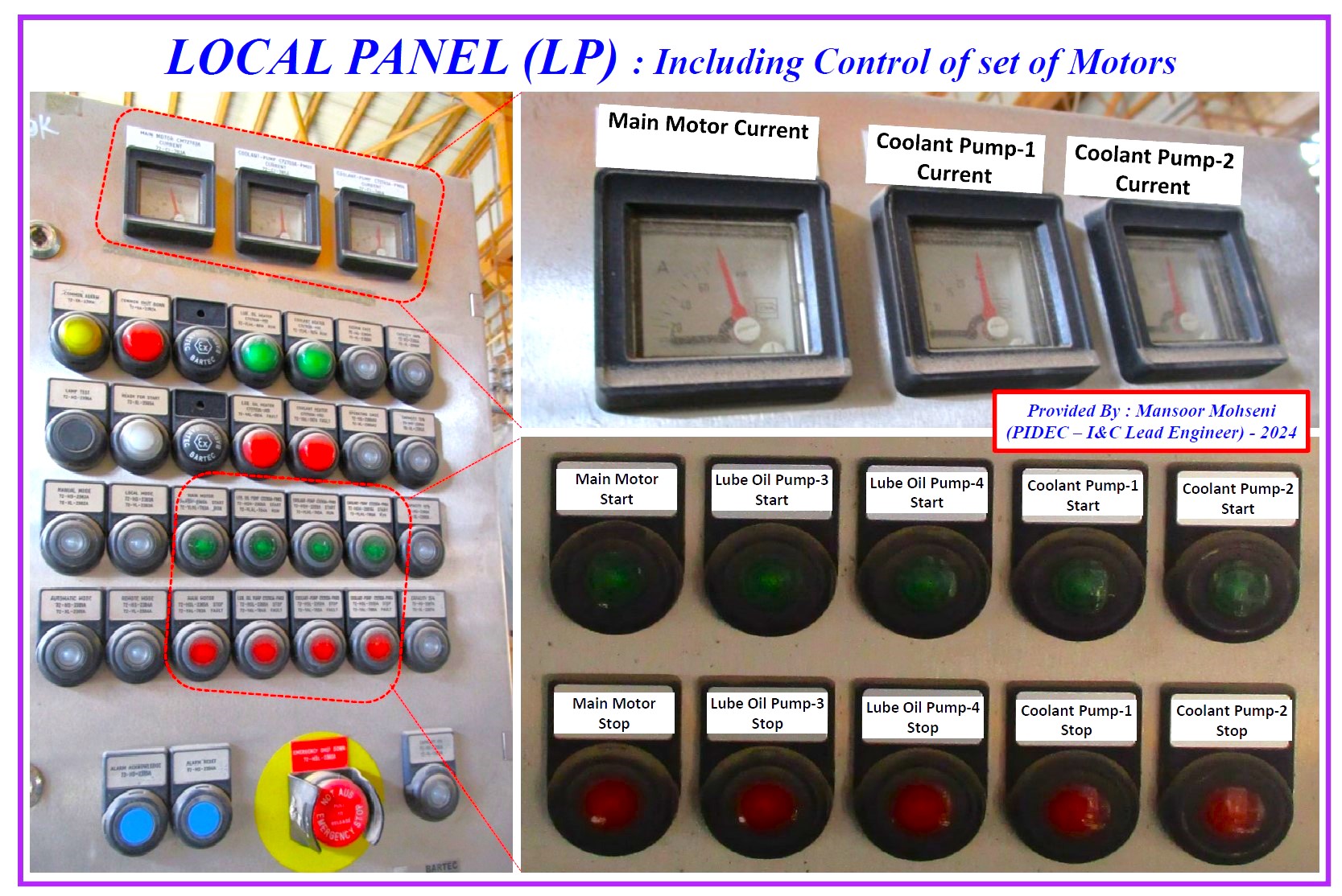
Figure-11: Example of Local Panel (LP) including control of a set of Motors.
Regarding Motor Control signals relevant to UCP and LP the below items may be mentioned:
- Control of Motors inside the packages may be done by Unit Control Panel (or PLC Panel) instead of DCS/ESD systems by using Plant MCC with a similar philosophy (or dedicated agreements or even they may have their own MCC panels).
- For some (limited) cases Package Local Panels will have the role of LCS too (and so there is no LCS in the field). In each package, it is possible to use both philosophies. (See Figure-11)
Conclusion
For controlling the Motors inside Process Plants, some interface signals from different locations (and systems) and some rules and procedures shall be considered briefly mentioned in Figure-12.
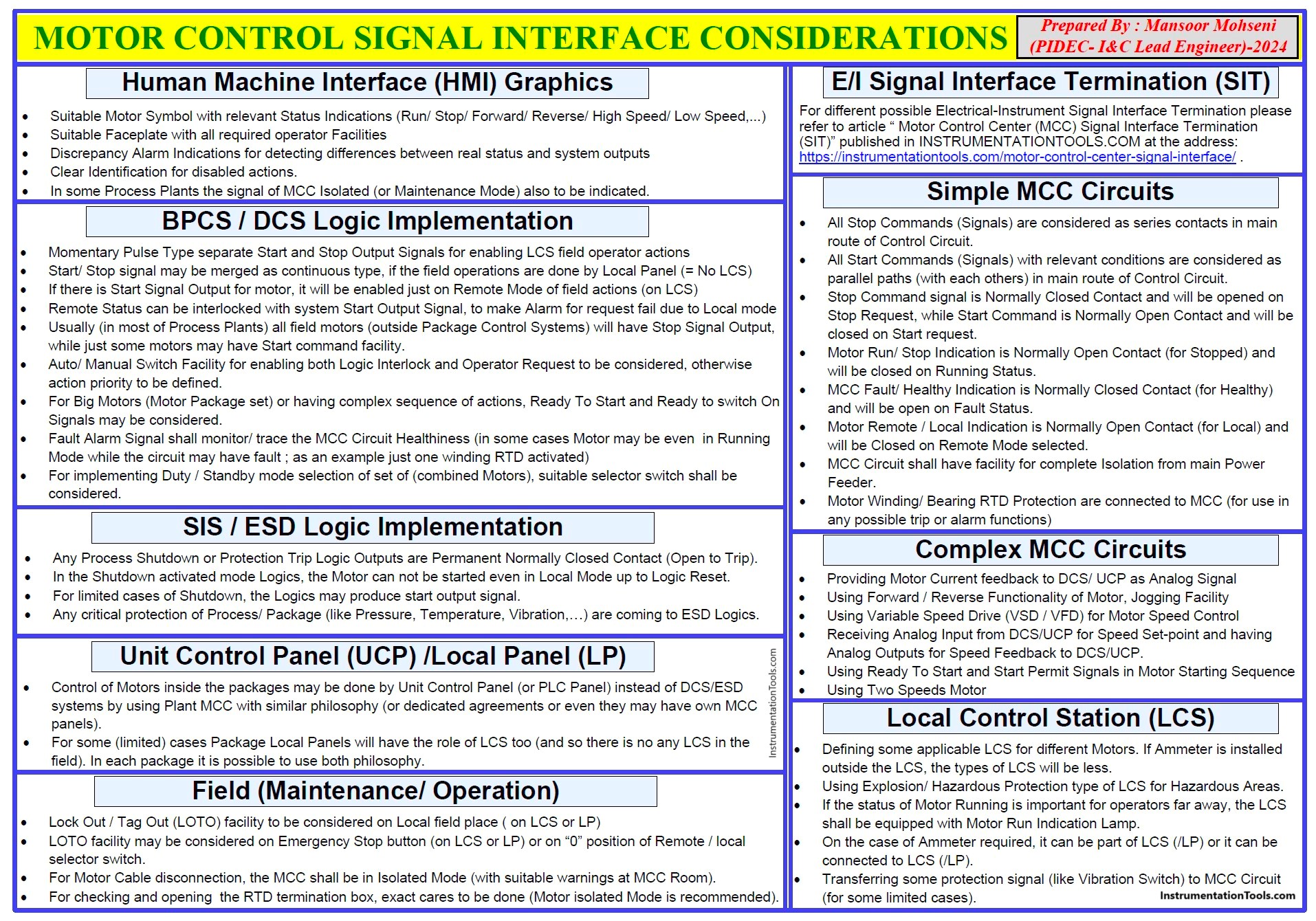
Figure-12: Summary of MOTOR CONTROL SIGNAL INTERFACE CONSIDERATIONS.
References:
- Instrumentation and Electrical Detail Design Engineering
- Motor Control Center Signal Interface Termination
- Package Control and Safety Systems Implementation
- Interactions With Process Control Systems Philosophy
