Modbus communication of delta PLC (DVP 14SS2) with delta VFD (VFD-L series). The motor is to be run directly from HMI (DOP-107CV) using Modbus communication.
The detailed parameters to be set for the communication mode are as follows:
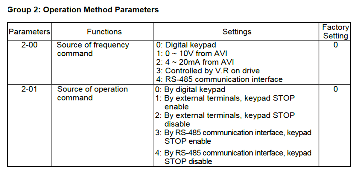
We have to set the communication parameters as per the above table. (taken from manual).
DVP 14SS2 has two communication ports namely RS232 and RS485 separately. Now, the communication port 2 settings need to be done according to the set parameters of VFD which are as follows.
Select COM2 and press next.
Set the parameters according to the VFD drive communication parameters and click Next. Here, they are fed according to the parameters set in the VFD-L dive.
The station address of PLC is 1 (see left bottom corner)
Check the highlighted and press next.
One can check the boxes below and write the conditions.
Here, we are skipping this window, and instead, we will write the logic directly on ladder diagram mode.
Click Finish.
Now, the following ladder logic is generated as a result of the above set conditions.
In this topic, we are here to use the decimal format for the particular address. So hexadecimal must be changed to decimal format.
Through the 8421 code, we would convert as follows:
So, instead of 200H & 2001H, 8192K & 8193K will be used. Make sure that 8192 & 8193 are only the Modbus addresses.
MODRW K2 K6 K8192 D70 K1
10 (dec) and 1 (dec) are moved to D70 when start and stop commands are given in rungs 6 and 7. At the same time, the transmission of data takes place i.e data in D70 is written to the 8192k address of VFD in rung 8 to start and stop the motor.
100 (dec) is added to D100’s value in rung 10 to increase the speed by 1 Hz when the speed increase pulse (M4) is received. 100 (dec) is subtracted from D100’s value in rung 9 to decrease the speed by 1 Hz when the speed decrease pulse (M5) is received.
At the same time, the transmission of data takes place i.e data in D100 is written to the 8193k address of VFD in rung 11 to start and stop the motor.
Now, coming to the HMI configuration.
After selecting the HMI model, set the below configuration as here, PLC to HMI configuration is on RS232. (You have to configure it as per the HMI model)
Take four momentary buttons, assign the addresses, and design the HMI screen as follows:
The HMI design is not covered in this article.
The below Delta PLC and VFD training topic is shared for your understanding. This is another way of controlling the motor speed via Delta PLC using ISPsoft.
If you liked this article, then please subscribe to our YouTube Channel for Instrumentation, Electrical, PLC, and SCADA video tutorials.
You can also follow us on Facebook and Twitter to receive daily updates.
Read Next:
In the PLC timer application for security camera recording, when motion is detected then camera…
In this example, we will learn batch mixing with PLC ladder logic program using timer…
This PLC example on manufacturing line assembly is an intermediate-level PLC program prepared for the…
In this article, you will learn the PLC programming example with pushbutton and motor control…
This article teaches how to convert Boolean logic to PLC programming ladder logic with the…
In this article, you will learn the PLC programming example on timers function block using…


View Comments
Hello Sir,
Sir your blog is good and interested can you please write a blog on delta b2 servo motor modbus communication with plc
Thanks mama....We are here to help you... If you want we can also make your project.