In many industrial automation projects, PLC logic appears flawless during commissioning, but only because the mechanical system is unintentionally covering up programming weaknesses. Actuator stroke times, motor coast-down delays, valve opening lags, and conveyor inertia can temporarily compensate for missing interlocks, improper sequencing, or absent feedback checks.
PLC Program Errors
The system runs smoothly, giving a false sense of correctness. However, once production speed increases, components are upgraded, or process conditions change, these hidden logic flaws surface abruptly. What seemed stable was actually a mechanical delay masking a control design gap; a risky situation in real plants, which will be seen in this post.
Output sequencing that relies on physical lag
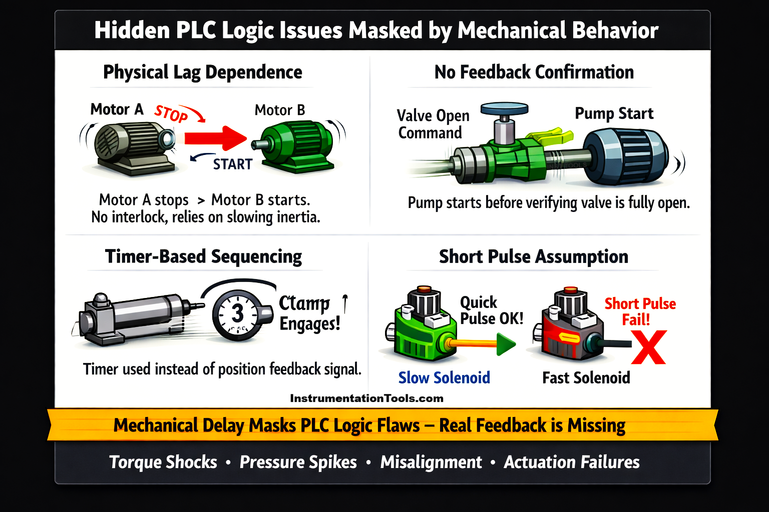
A common hidden PLC logic issue occurs when output sequencing depends unintentionally on mechanical inertia rather than proper interlocking. Consider a program that stops Motor A and immediately starts Motor B, without verifying that Motor A has fully stopped (no zero-speed feedback, no auxiliary contact confirmation, no status check from the VFD).
Logically, this is incomplete sequencing. However, in real plant conditions, Motor A does not stop instantly; it coasts down over 2-3 seconds due to mechanical inertia and load. That gradual deceleration unintentionally softens the transition. When Motor B starts, the overlapping motion does not immediately create torque shock, belt stress, or gear impact because the system is mechanically forgiving. The inertia absorbs the sequencing gap.
The problem appears later when plant conditions change. If a brake is added, deceleration time in the drive is reduced, a lower-inertia motor is installed, or load conditions change, Motor A may now stop much faster. Since the PLC logic still starts Motor B immediately without confirmation, the transition becomes abrupt. This can cause sudden torque differences, mechanical jerks, backlash impact, or belt tension spikes. The original system seemed stable only because the mechanical delay was masking the missing interlock. The logic was never truly correct, but the mechanical softness was compensating for it.
Missing feedback confirmation
Another way mechanical delay masks PLC logic errors is when commands are issued without verifying actual field feedback. For example, the PLC sends a command to open a control valve and immediately starts a pump or enables the next process step without checking the valve’s open limit switch or position feedback.
Logically, this is unsafe sequencing because the system assumes the valve has opened just because the command was given. However, in many plants, the valve actuator takes 1-2 seconds to physically move to the open position, and the pump may also ramp up slowly due to VFD acceleration time. These combined mechanical and drive delays unintentionally synchronize the system. Everything appears normal because by the time full flow or pressure builds, the valve has already reached its open position.
The hidden flaw becomes visible when conditions change. If a faster actuator is installed, pipeline volume is reduced, pump acceleration time is shortened, or process pressure increases, the timing relationship shifts. The pump may build pressure before the valve is fully open, leading to pressure spikes, water hammer, or mechanical stress on the piping. The PLC logic never verified the real-world condition, but it only assumed execution. Previously, mechanical lag covered the gap. Once that lag reduces, the sequencing weakness is exposed.
Timer-based logic instead of status-based logic
A common masking situation occurs when PLC logic relies on fixed timers instead of actual position feedback. For example, the program energizes a pneumatic cylinder extended output and then starts a 3-second timer before activating a clamp or the next motion step.
During commissioning, this works because the cylinder normally extends in about 2 seconds under proper air pressure and load. The extra one-second margin makes the sequence appear safe. However, the PLC is not verifying the extended position through a limit switch or proximity sensor; it is simply assuming the motion will always complete within that fixed time.
The real issue becomes visible when air pressure drops, load increases, seals wear, or friction rises. Now the cylinder may take longer than 3 seconds to fully extend, but the clamp still activates when the timer finishes. This can lead to partial clamping, part misalignment, mechanical stress, or even component damage. Earlier, stable air pressure and consistent mechanics were masking the weakness in logic. The timer was never a guarantee, but it was just a guess based on ideal conditions. Once those conditions degrade, the flaw is exposed.
Scan-time and pulse width assumptions
Another subtle way mechanical behavior can mask PLC logic errors is through improper pulse handling. In some programs, an output bit may be turned ON and then reset quickly within the logic, sometimes lasting only a few PLC scans, due to missing latching, poor sequencing, or transitional logic errors. Electrically, this creates a very short pulse at the output module. From a control logic perspective, this is unstable and poorly defined. However, the field device connected to that output may not respond purely based on pulse duration alone; its electromagnetic and mechanical characteristics also play a role.
In conventional solenoid valves, the coil has inductance, meaning current does not instantly rise or fall. When energized, the magnetic field builds with a small time constant, and when de-energized, it does not collapse immediately. The armature has physical mass, a softer spring return, and sometimes magnetic remanence (residual magnetism). Because of these factors, even a short electrical pulse may generate enough magnetic force to start moving the armature. Once movement begins, inertia and residual magnetic force may allow the valve to complete its stroke even after the PLC output turns OFF. The mechanical system unintentionally smooths out the short pulse.
However, if that same valve is replaced with a high-speed solenoid designed for fast response, the behavior changes. High-speed devices typically have lower inductance, lighter moving parts, stronger return springs, and minimal magnetic retention. They require a clearly defined minimum pulse width to fully actuate. If the PLC output pulse is too short, the armature may start to move but immediately snap back when the magnetic field collapses. The device will not actuate reliably. In this case, the original system appeared stable, not because the logic was correct, but because the slower electromechanical characteristics were compensating for poor pulse definition. Once faster, more precise hardware is introduced, the weakness in PLC signal handling becomes exposed.