By using this site, you agree to the Privacy Policy and Terms of Use.
Accept
Inst ToolsInst ToolsInst Tools
  • Ask
  • Courses
  • Videos
  • Q & A
    • Interview
      • Instrumentation
      • Electronics
      • Electrical
      • Practical Questions
    • MCQ
      • Instrumentation MCQ
      • Electrical MCQ
      • Electronics MCQ
      • Control Systems MCQ
      • Analog Electronics MCQ
      • Digital Electronics MCQ
      • Power Electronics MCQ
      • Microprocessor MCQ
      • Multiple Choice Questions
  • EE
    • Electronics
      • Electronics Q & A
      • Electronic Basics
      • Electronic Devices & Circuits
      • Electronics Animation
      • Digital Electronics
    • Electrical
      • Electrical Basics
      • Electrical Q & A
      • Power Electronics
      • Electrical Machines
      • Electrical Animation
      • Power Systems
      • Switchgear & Protection
      • Transmission & Distribution
  • Measure
    • Control Valves
    • Calibration
    • Temperature
    • Pressure
    • Flow
    • Level
    • Analyzers
    • Switches
    • Vibration
    • Solenoid Valve
  • Control
    • PLC Tutorials
    • Control Systems
    • Safety Instrumented System (SIS)
    • Communication
    • Fire & Gas System
  • More
    • Design
    • Tools
    • Animation
    • Basics
    • Formulas
    • Standards
    • TextBooks
    • Common
    • Software
    • Excel Tools
    • Erection & Commissioning
    • Process Fundamentals
    • Videos
    • Books
Search
All rights reserved. Reproduction in whole or in part without written permission is prohibited.
Reading: Magnetic Flow Meter Animation
Share
Notification Show More
Font ResizerAa
Inst ToolsInst Tools
Font ResizerAa
  • Ask
  • Courses
  • Videos
  • Q & A
  • EE
  • Measure
  • Control
  • More
Search
  • Ask
  • Courses
  • Videos
  • Q & A
    • Interview
    • MCQ
  • EE
    • Electronics
    • Electrical
  • Measure
    • Control Valves
    • Calibration
    • Temperature
    • Pressure
    • Flow
    • Level
    • Analyzers
    • Switches
    • Vibration
    • Solenoid Valve
  • Control
    • PLC Tutorials
    • Control Systems
    • Safety Instrumented System (SIS)
    • Communication
    • Fire & Gas System
  • More
    • Design
    • Tools
    • Animation
    • Basics
    • Formulas
    • Standards
    • TextBooks
    • Common
    • Software
    • Excel Tools
    • Erection & Commissioning
    • Process Fundamentals
    • Videos
    • Books
Follow US
All rights reserved. Reproduction in whole or in part without written permission is prohibited.
Inst Tools > Blog > Animation > Magnetic Flow Meter Animation

Magnetic Flow Meter Animation

A mag meter or electromagnetic flow meter works on Faraday's Law of Electro-Magnetic Induction. See this Magnetic Flow Meter Animation.

Last updated: October 31, 2023 11:26 am
Editorial Staff
Animation Flow Measurement How It Works
14 Comments
Share
2 Min Read
SHARE

A magnetic flow meter (mag meter, electromagnetic flowmeter) is a transducer that measures fluid flow by the voltage induced across the liquid by its flow through a magnetic field.
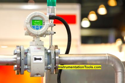
Contents
Magnetic Flow MeterPrinciple of Operation

Magnetic Flow Meter

Magnetic Flow Meter Animation

Image Courtesy: Yokogawa

A magnetic field is applied to the metering tube, which results in a potential difference proportional to the flow velocity perpendicular to the flux lines. The physical principle at work is electromagnetic induction.

The magnetic flow meter requires a conducting fluid, for example, water that contains ions, and an electrical insulating pipe surface, for example, a rubber-lined steel tube.

Principle of Operation

Simply, Magnetic Flow Meters work on Faraday’s Law of Electro-Magnetic Induction.

The Two Blue dots in the animation indicate electrodes. The Copper coils (red blocks – magnets) on top & bottom of the instrument are electro-magnets used to generate a magnetic field.

When there is no fluid flow then the induced voltage between electrodes is Zero.

When a fluid flows through the magnetic field, the two electrodes pick up the voltage and it is proportional to fluid flow rate.

That’s it. Very Simple.

Post your opinions on Instrumentation animations. Share it with your friends.

If you liked this article, then please subscribe to our YouTube Channel for Instrumentation, Electrical, PLC, and SCADA video tutorials.

You can also follow us on Facebook and Twitter to receive daily updates.

Read Next:

  • Magnetic Meters Complete Guide
  • Conductive Level Measurement
  • Why do Flow Meter Calibration
  • Flow Meter Square Root Relationship
  • Architecture of Instrumentation
Don't Miss Our Updates
Be the first to get exclusive content straight to your email.
We promise not to spam you. You can unsubscribe at any time.
Invalid email address
You've successfully subscribed !
Relay Working Animation
Mass Flow Calculations
Open Tank Level Measurement using DP Transmitters Animation
DP type Flow Transmitter Preventive Maintenance and Calibration
Comparison of Venturi and Orifice flow meter
Share This Article
Facebook Whatsapp Whatsapp LinkedIn Copy Link
Share
14 Comments
  • Dev says:
    July 23, 2015 at 1:42 am

    Five stars for instrumentation Animations and very useful website for instrumentation engineers.

    Reply
  • pankaj says:
    July 25, 2015 at 11:24 am

    it is useful to us…who work on field……

    Reply
  • Mohamad says:
    August 8, 2015 at 6:07 am

    When is it recommended to use the magnetic flowmeter? what are the best process conditions to be used for?? thanks

    Reply
    • S Bharadwaj Reddy says:
      August 19, 2015 at 4:58 am

      One unique aspect of magnetic flowmeters is that they can only measure conductive fluids. They are excellent for water and most other liquids, but they cannot measure hydrocarbon-based fluids.Some advantages of magnetic flowmeters are that they can easily handle dirty liquids, slurries, wastewater, and other hard-to measure liquids.

      Another unique feature of magnetic flowmeters is the number of types of liners available for different applications. These different liners make magnetic flowmeters useful for hygienic applications, for caustic liquids, and for almost any type of water application. Almost any type of conductive liquid can be measured with the right type of liner.

      Reply
      • Ashish says:
        September 22, 2017 at 10:50 pm

        Conductivity shall be checked with Process. Water conductivity is not very excellent. This was confirmed by Process Engineer. Because water can be many types like Fresh water, Sour water, Sea water etc. Caustic soda for example has very high conductivity.

        Reply
        • Mahtab says:
          October 5, 2023 at 12:05 pm

          As far as I know the electrical conductivity of the fluid should be more than 5 microsiemens.

          Reply
  • suresh says:
    November 24, 2015 at 2:18 pm

    Very useful…

    Reply
  • Shefeek Salim says:
    February 29, 2016 at 5:50 pm

    Magnetic types are very accurate,but if there is any electrical disturbances like as improper earthing etc,that will badly affect the signals from the sensor to transmitter,and transmitter may unable to produce exact output PV.

    Reply
  • Nishant Sohani says:
    May 23, 2016 at 3:50 am

    Very nice good information I like it

    Reply
  • Agravat says:
    May 27, 2016 at 12:24 pm

    What type of output current a.c. or D.C.? ??

    Reply
  • Eduardo says:
    January 22, 2017 at 2:01 pm

    Dear sir. I can’t explain how wonderful and useful your website is. Thank you very much for your work.

    Best regards.

    Reply
  • Antonio Gingado says:
    December 16, 2017 at 2:52 pm

    simplesmente MARAVILHOSO

    Translated Portuguese to English : just wonderful

    Reply
  • sunil says:
    July 22, 2019 at 11:40 am

    Your animation explains everything!
    No need for any text!

    Reply
  • Tushar says:
    April 24, 2021 at 7:04 pm

    Hello
    Very nice animation. I would like to show animation in my college project. I eager to know Which software do you guys use to create such animation?

    Reply

Leave a Reply Cancel reply

Your email address will not be published. Required fields are marked *

Stay Connected

128.3kFollowersLike
69.1kFollowersFollow
208kSubscribersSubscribe
38kFollowersFollow

Recent Comments

  • MIHARITSOA Aina Sitraka on Top Non-PLC Certification Courses for Automation Professionals
  • Vaishnavi on Free Instrumentation Course for Trainee Engineers
  • anuj kapoor on DCS Program to Maintain Draft in Furnace
  • anuj kapoor on IoT based Smart Boiler Control System with Cloud PLC and SCADA

Related Articles

positive displacement flow meter pictures

What is a Positive Displacement Flow Meter?

DP type Flow Transmitter Preventive Maintenance

Troubleshooting DP type Transmitter Common Problems

Types of Flow Meters

Types of Flow Meters

Proximity Switch PNP Type Working Animation

Proximity switches Circuit Diagram Operation

Pressure based Flowmeters

Pressure based Flow Meters

NO NC Contact Animation

Equivalent Logic Gates using PLC Ladder Diagrams

Dall Tube Flow Meter Working Principle

Dall Tube Flow Meter – Principle, Advantages, Disadvantages

AND Gate Logic Animation

Digital Building Blocks – GATES

More Articles

Feedback Characteristics of Control Systems

Control of the Effects of Disturbance Signals by Use of Feedback

pH Analyzers Questions and Answers

pH Meters Questions & Answers

Types of PLC

Types of PLC

Selection of Fire and Gas Detectors

Basic Guidelines for Selection of Fire and Gas Detectors

Pulse Timer Instruction in PLC Programming

Pulse Timer Instruction in PLC Programming

What is SMPS

What is SMPS? – Types of SMPS

Magnatic Level Indicators Working Animation

Magnetic Level Indicators Working Animation

PLC Program for Star Delta Starter using Functional Block Diagram

PLC Program for Star Delta Starter using Functional Block Diagram

Follow US
All rights reserved. Reproduction in whole or in part without written permission is prohibited.
Welcome Back!

Sign in to your account

Username or Email Address
Password

Lost your password?