Here we shall learn about Magnetic flow meter basics and installation requirements.
The electromagnetic flowmeter is used to measure the flow of conductive liquids and slurries as low as 5 Micro Siemens (including corrosive and abrasive) in closed pipes.
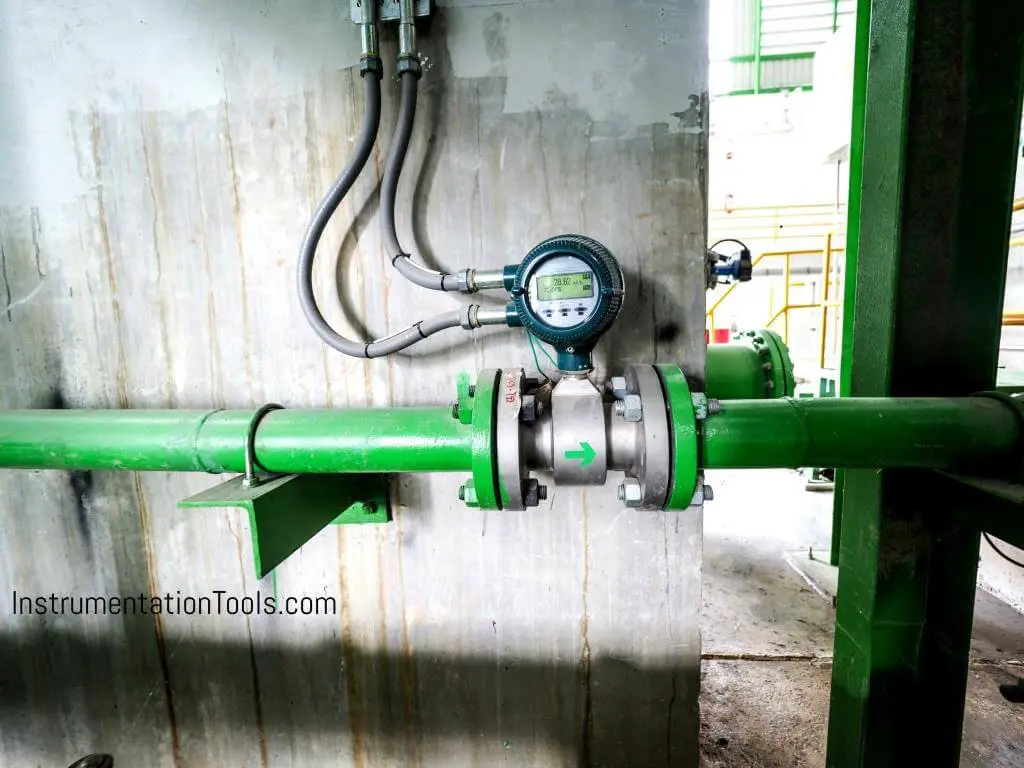
Magnetic Flow Meters
The performance of the instrument is not affected by the properties of the material such as corrosiveness, viscosity, pressure, density, acidity, and alkalinity.
It can measure the flow of liquids, pastes, and slurries in water, wastewater, chemical, fertilizer, dairy, food, beverage, pharmaceutical, medical, petrochemical, iron, steel, paper, mining, and agricultural industries, etc.
They are used to measure water flow cooling in steel and power plants. They have the ability to measure the flow of clean water, effluent, sludges, etc., in pollution and environmental control.
Installation Guidelines
The flow sensor must be mounted in a location that is free from interfering elements like valves, Ts, bends, pumps, etc. to ensure a laminar flow without turbulence upstream of the flow sensor.
For that reason, the flow sensor must be mounted in a straight pipe at a distance from interfering elements of minimum 3 x DN upstream and minimum 2 x DN downstream.
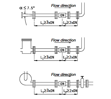
Important: Valves should always be mounted on the downstream side of the flow sensor.
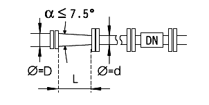
If it becomes necessary to use reducers, the inner angle must not exceed 7.5°. The minimum length to keep the angle below 7.5° can be checked by means of the formula below:
L = (D – d) x 7.63
where “D” is the large diameter and “d” the small diameter of the reducer.
Also Read:
Example Setup
If a flow sensor in dimension DN 80 is mounted downstream of a 100 mm pipe, the reducer must then have a length of minimum 152.6 mm in order to keep the inner angle below 7.5 °.
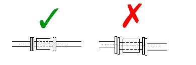
Flange connections must be assembled concentrically on both the upstream and the downstream side. Measuring accuracy will be affected by turbulence in the liquid from poorly made connections.
Important: Gaskets and grounding rings must also be mounted concentrically!
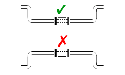
The flow sensor should always be filled with liquid. For that reason, the flow sensor must not be mounted at the highest point of the pipe system or in free outlets, where gravity could empty or partially empty the pipe.
The flow sensor can be mounted vertically or horizontally. If the flow sensor is mounted vertically, the flow direction should always be upwards.
In that way, the effect of possible bubbles in the liquid will be significantly reduced, just as it will ensure that the flow sensor is always filled with liquid. In case the liquid is carrying particles, for example when measuring sludge, sewage, etc., the flow sensor must be mounted vertically.
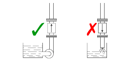
When mounting horizontally in pipes with the free downstream outlets, the flow sensor should be mounted such that it will always be filled with liquid, for example in a bend situated lower than the height of the outlet.
In case the liquid is carrying particles, e.g. when measuring sludge, sewage, etc. the flow sensor must be mounted vertically.
Interest to add any further points? Share with us through below comments section.
Author: Kalpit Patel
If you liked this article, then please subscribe to our YouTube Channel for Instrumentation, Electrical, PLC, and SCADA video tutorials.
You can also follow us on Facebook and Twitter to receive daily updates.
Read Next:
- Electrical Heat Tracing
- Orifice Plate Design Rules
- Design of Level Gauges
- Variable Area Flow Meter
- All About Turbine Meter


this is very nice also include the working principle of magnetic flow meter
Very good – I’ve just been reading the MagFlux manual from where this information has been taken (Installation and User Manual 0900766b816627dc)
sir we are installed magnetic flowmeter 6″ in river jack well pump discharge using u syphon 1-meter upstream & downstream length flowmeter line size is 20″ to storage tank around 2 km flow showing higher please give cross checking method