Write a PLC program to run a motor in case that when the first Push Button (PB) is pressed the motor runs in a latched mode, when the second PB is pressed the motor will not be in the latched mode and will be in the momentary mode and when the stop PB is pressed the motor should be stopped.
Note: the best practice to learn the PLC programming is to start writing the PLC program, take your time before you review the answer.
Inputs and outputs:
I0.0: First Push Button (Normally open contact)
I0.1: Second Push Button (Normally open contact)
I0.2: Stop Push Button (Normally Closed Contact)
Q0.0: Motor
M0.0: marker for SR flip flop
M0.1: marker for positive edge
Latched and Momentary Operation of Motor
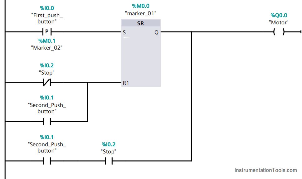
PLC Program Explanation
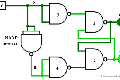
In order to keep the motor latched you can use the SR flip flop where the set branch is energized by positive edge detection from the First_push_button, and the reset branch is energized by either the stop_push_button or the Second_push_button is energized.
The second_push_button is connected to the stop normally open (in this case normally open is the reverse case of the Stop_push_button) in order to not operate the motor in the case of the stop_push_button is pressed.
Author: Karim Ali Anwar
If you liked this article, then please subscribe to our YouTube Channel for PLC and SCADA video tutorials.
You can also follow us on Facebook and Twitter to receive daily updates.
Read Next:
- Types of Cables
- Start Stop Motor Logic
- 100 Motor Quiz Questions
- PLC and VFD Circuit Problem
- Run Motors Sequential