Design Ladder Logic for Stair-Case wiring using two Toggle Switches in programmable logic controllers (PLC).
- I0.0 & I0.1 : Input toggle switches.
- Q0.0 : Output signaling device(bulb, motor etc.)
Ladder Logic for Stair-Case wiring
This ladder logic of stair-case wiring works on the X-OR logic i.e, Y is (A.B^) + (A^. B)
Suppose initially only I0.0 is pressed and I0.1 remains open physically as shown then the upper branch of rung 1 goes TRUE and Q0.0 gets energized.
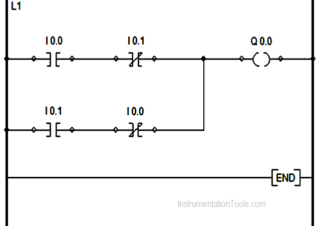
Now , if I0.0 is also pressed then it will make its interlock N-C contact I0.1 to go open and as a result Q0.0 de-energizes .
Again, if switch I0.0 is pressed it will also make its interlock contact I0.0 in parallel branch to go again N-C , which in turn makes the parallel branch logic true and Q0.0 again energizes but if the I0.1 input is also pressed again the logic goes FALSE and Q0.0 again de-energizes. This is the basic concept of an X-OR logic gate.
If you liked this article, then please subscribe to our YouTube Channel for PLC and SCADA video tutorials.
You can also follow us on Facebook and Twitter to receive daily updates.
Read Next:
Motor Start Stop Logic using PLC
