Inst ToolsInst ToolsInst Tools
  • Courses
  • Automation
    • PLC
    • Control System
    • Safety System
    • Communication
    • Fire & Gas System
  • Instrumentation
    • Design
    • Pressure
    • Temperature
    • Flow
    • Level
    • Vibration
    • Analyzer
    • Control Valve
    • Switch
    • Calibration
    • Erection & Commissioning
  • Interview
    • Instrumentation
    • Electrical
    • Electronics
    • Practical
  • Q&A
    • Instrumentation
    • Control System
    • Electrical
    • Electronics
    • Analog Electronics
    • Digital Electronics
    • Power Electronics
    • Microprocessor
  • Request
Search
  • Books
  • Software
  • Projects
  • Process
  • Tools
  • Basics
  • Formula
  • Power Plant
  • Root Cause Analysis
  • Electrical Basics
  • Animation
  • Standards
  • 4-20 mA Course
  • Siemens PLC Course
Reading: What is Interface Module in Siemens PLC?
Share
Font ResizerAa
Inst ToolsInst Tools
Font ResizerAa
  • Courses
  • Design
  • PLC
  • Interview
  • Control System
Search
  • Courses
  • Automation
    • PLC
    • Control System
    • Safety System
    • Communication
    • Fire & Gas System
  • Instrumentation
    • Design
    • Pressure
    • Temperature
    • Flow
    • Level
    • Vibration
    • Analyzer
    • Control Valve
    • Switch
    • Calibration
    • Erection & Commissioning
  • Interview
    • Instrumentation
    • Electrical
    • Electronics
    • Practical
  • Q&A
    • Instrumentation
    • Control System
    • Electrical
    • Electronics
    • Analog Electronics
    • Digital Electronics
    • Power Electronics
    • Microprocessor
  • Request
Follow US
All rights reserved. Reproduction in whole or in part without written permission is prohibited.
Inst Tools > Blog > PLC Tutorials > What is Interface Module in Siemens PLC?

What is Interface Module in Siemens PLC?

In this article, we will learn about the interface module (IM) used in the Siemens PLC for data transfer between I/O modules or between PLCs.

Last updated: March 4, 2021 11:18 am
Editorial Staff
PLC Tutorials
No Comments
Share
4 Min Read
SHARE

In this article, we will learn about the interface module (IM) used in the Siemens PLC.

The data transfer between I/O modules or between higher levels of PLCs takes place via an interface module.

I know that many people have heard this word remote I/O, this is achieved by installing an interface module.

Remote I/O is used to reduce long wire run, reduce complexity while troubleshooting, and provide a cost-effective solution.

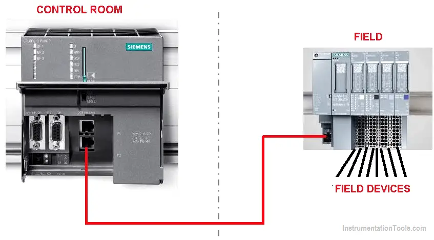
Let’s assume that in the plant we have to install a bunch of field devices that are far away from the control room.

In such a case instead of pulling wires from field to control room can increase the cost significantly and also make troubleshooting of a system more difficult.

To make things simple, first, move all the I/O modules to the field area and add interface module with it.

Now, connect supported communication port from the control room’s CPU to interface module to establish communication with each other.

This way you only require one cable for communication between devices, which reduces the cost of wiring and complexity.

Interface Module in Siemens PLC

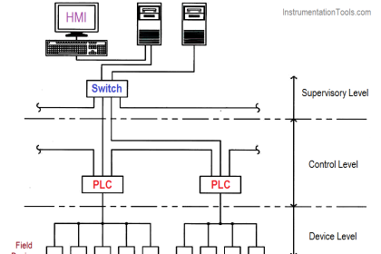
As you can see in the below image that how an interface module is used to transfer data over a long distance.

In the case of a critical system, you can pull one more communication cable as a redundant system to prevent an unexpected shutdown.

Redundant system communication cable

There is one more way to use the interface module in the control panel.

In s7-300 series of CPU support three rack and eleven module configurations.

If you have a larger system than you may require more than one rack to communicate with other racks, Here, you need an interface module.

Check out the below image to know how an interface module is added on the rack to communicate with the CPU.

As you can see Interface module is added to the second slot of a first rack and in the first slot of the second rack.

Pull PROFIBUS cable from the first IM to the second IM. This way it can communicate with the rack through two Interface modules.

Interface Module in Siemens PLC

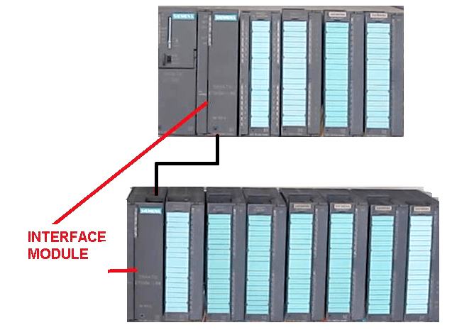
This way you can add the third rack and do follow the same step to establish a connection.

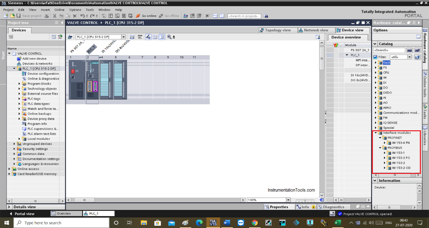
On the software side, you can find many different types of interface modules. You can choose as per your application and hardware.

You can connect an interface module through PROFINET or by PROFIBUS method to communicate.

Siemens Interface Module

Author: Suhel Patel

If you liked this article, then please subscribe to our YouTube Channel for PLC and SCADA video tutorials.

You can also follow us on Facebook and Twitter to receive daily updates.

Read Next:

  • Electrical Ground Loop
  • Components of PLC
  • Fieldbus Coupling Devices
  • PLC Sinking and Sourcing
  • Test and Process Modes
Don't Miss Our Updates
Be the first to get exclusive content straight to your email.
We promise not to spam you. You can unsubscribe at any time.
Invalid email address
You've successfully subscribed !

Continue Reading

PLC based Gas Detection System using Ladder Logic Project
PLC Programming Videos
Types of Instructions in PLC Programming
CX-Programmer Products Sorting & Counting – Omron PLC
Exhaust Fan Control: Example of PLC Timer Programming
Introduction to PLC – Advantages of PLC
Share This Article
Facebook Whatsapp Whatsapp LinkedIn Copy Link
Share
Leave a Comment

Leave a Reply Cancel reply

Your email address will not be published. Required fields are marked *

Stay Connected

128.3kFollowersLike
69.1kFollowersFollow
210kSubscribersSubscribe
38kFollowersFollow

Categories

Explore More

Draw a Ladder Logic to switch ON-OFF a Bulb using a Toggle Switch ?
Communicating Delta PLC Software to Simulator
How to Communicate with Excel from Intouch SCADA?
ON Delay Timer using PLC
PLC Programming for Train Detection and Gate Operation
How-to do Security of SCADA Systems?
Structured Text PLC Code for Sequential Process Data Storage
PLC Electric Motor Interlocks

Keep Learning

What is a GSD File and Why it is required?

What is a GSD File and Why it is required?

How to Create DFB in Schneider PLC? – Derived Function Block

Siemens PLC-to-PLC Communication Project

GET Command – Siemens PLC-to-PLC Communication Project

How to Program Sequential Outputs in PLC

Timer-Based Sequential PLC Program with One Button

Create an Application in HMI using Tia Portal

Create an Application in HMI using Tia Portal

PLC Best Practices

#1 PLC Best Practices – Split PLC Code into Modules

PLC Raw Count Calculation formula for Pressure Transmitter

PLC Raw Count Calculation for Pressure Transmitter

CODESYS HMI Interface

CODESYS HMI Interface

Learn More

Instrument Technician Questions and Answers

Instrument Technician Questions and Answers

Relay Types

Types of Relays – Questions and Answers

Replace Failed Motors Quickly and Easily

Replace Failed Motors Quickly and Easily

Siemens Process Mode

Test and Process Modes in Siemens PLC

Instrumentation Loop Diagram

Loop diagram and System Inspection Lab Exercise

Open Loop Control Block Diagram

Self-regulating Processes – Liquid Flow Control

Center Tap Full-Wave Rectifier

Full-Wave Rectifier Circuit

Robotic Process Automation

What is Robotic Process Automation? Advantages, Applications

Menu

  • About
  • Privacy Policy
  • Copyright

Quick Links

  • Learn PLC
  • Helping Hand
  • Part Time Job

YouTube Subscribe

Follow US
All rights reserved. Reproduction in whole or in part without written permission is prohibited.
Welcome Back!

Sign in to your account

Username or Email Address
Password

Lost your password?