Inst ToolsInst ToolsInst Tools
  • Courses
  • Automation
    • PLC
    • Control System
    • Safety System
    • Communication
    • Fire & Gas System
  • Instrumentation
    • Design
    • Pressure
    • Temperature
    • Flow
    • Level
    • Vibration
    • Analyzer
    • Control Valve
    • Switch
    • Calibration
    • Erection & Commissioning
  • Interview
    • Instrumentation
    • Electrical
    • Electronics
    • Practical
  • Q&A
    • Instrumentation
    • Control System
    • Electrical
    • Electronics
    • Analog Electronics
    • Digital Electronics
    • Power Electronics
    • Microprocessor
  • Request
Search
  • Books
  • Software
  • Projects
  • Process
  • Tools
  • Basics
  • Formula
  • Power Plant
  • Root Cause Analysis
  • Electrical Basics
  • Animation
  • Standards
  • 4-20 mA Course
  • Siemens PLC Course
Reading: Instrumentation Cables Armor
Share
Font ResizerAa
Inst ToolsInst Tools
Font ResizerAa
  • Courses
  • Design
  • PLC
  • Interview
  • Control System
Search
  • Courses
  • Automation
    • PLC
    • Control System
    • Safety System
    • Communication
    • Fire & Gas System
  • Instrumentation
    • Design
    • Pressure
    • Temperature
    • Flow
    • Level
    • Vibration
    • Analyzer
    • Control Valve
    • Switch
    • Calibration
    • Erection & Commissioning
  • Interview
    • Instrumentation
    • Electrical
    • Electronics
    • Practical
  • Q&A
    • Instrumentation
    • Control System
    • Electrical
    • Electronics
    • Analog Electronics
    • Digital Electronics
    • Power Electronics
    • Microprocessor
  • Request
Follow US
All rights reserved. Reproduction in whole or in part without written permission is prohibited.
Inst Tools > Blog > Erection & Commissioning > Instrumentation Cables Armor

Instrumentation Cables Armor

Armor in the cable construction is used as physical or mechanical protection so that the cable wouldn’t damage from harsh mechanical impact.

Last updated: October 12, 2020 1:18 pm
Editorial Staff
Erection & Commissioning
No Comments
Share
5 Min Read
SHARE

Single-pair or Multi-pair Cables

The general types of instrumentation cables are single-pair or multi-pair/tripple cables used to carry electrical signals between different instruments, controllers, PLC, DCS, etc.

Contents
Single-pair or Multi-pair CablesControl CablePower CableThermocouple CableCable Construction StandardsArmorTypes of JacketTypes of Armoring

The single-pair or multi-pair cables are twisted such that it reduces the effects of electromagnetic interference (EMI) from external sources. These also helps to reduce the cross talk between neighboring pair cables.

The individually shielded pair construction is typically used for analog signals and the construction with total shield only is used for digital signals.

The triad cables are also used for connecting the 3 wire RTD’s and respective transmitters. In some applications, triad cables are used for connecting the RTD’s mounted on the high-capacity motors and temperature scanners.

Instrumentation Cables

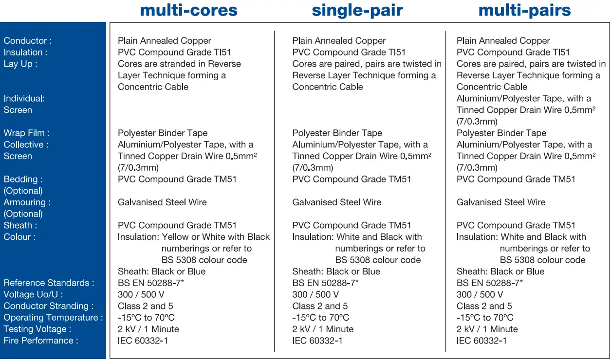
Image Courtesy: lkhpd

Control Cable

The control cables are generally a multi-condctor cables used for the control circuit applications like for example controlling of solenoid valves, compressors, etc.

These are generally used to send or receive ON or OFF signals like for example start/stop commands, open/close feedbacks, permissive or trip signals.

The nature of the type of the signal (on/off) do not require special precaution in terms of shielding and twisting of pairs, in fact the assembling of cores have a simple multi-core structure.

Power Cable

A power cable is used for transmission of electrical power.

They are typically composed up to five conductors for the following purposes:

  • 3 cores for each phase (R, S, T)
  • 1 core for neutral (N)
  • 1 core for protection earth (PE)

Thermocouple Cable

The thermocouple cables are used for connecting the thermocouples and the field transmitters. These cables are made from the same alloys as like thermocouple. There are different thermocouples available with different material constructions, so similarly themocouple extension cables are also available in different material constructions. The thermocouple extension cables are costly as they use same material for construction.

The compensating cables are also available where they use similar materials which provides approximate emf output for the measured temperature range. These are cheap but less accurate when compared to extension cables.

Cable Construction Standards

  • IEC 502 600/1000 Volt for PVC & XLPE insulations
  • IEC 227 450/750 Volt for PVC insulation
  • BS 5308 300/500 Volt for PVC & HDPE insulations
  • BS 6346 & 5467 600/1000 Volt for PVC & XLPE insulations

Armor

The armor in the cable protects the cable from the physical damages, mechanical forces, and other vibration shocks.

The general type of armor are steel wire armored (SWA), steel wire braid (SWB), and steel tape armored (STA)

Typically, the construction of an aluminium or steel wire armored cable comprises six components:

  • Conductor: plain stranded copper or aluminium
  • Insulation: materials such as cross-linked polyethylene (XLPE) provide high temperature resistance and excellent dielectric strength-providing enhanced electrical properties.
  • Bedding: a layer to create a protective barrier between the insulation and the armour.
  • Armour: a steel or aluminium armour provides mechanical protection to allow the cable to withstand the mechanical stresses to which it is exposed.
  • Sheath: the constituent parts of the cable are held together by a sheath offering a further level of protection. Black sheaths can be carbon-loaded for UV stability.
  • Voltage: voltage ratings of 600/1000V, 6.35/11kV and 19/33kV.

The below image represents a Individual and Overall Shielded cable.

Instrumentation Cables Armor
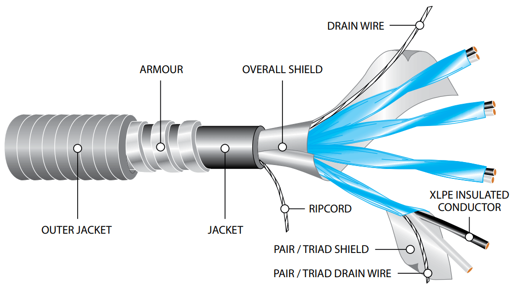
Image courtesy: Texcan

  • Conductors: Class B stranded bare copper per ASTM B-3 and B-8
  • Insulation: Premium Grade Polyvinyl Chloride (PVC) plus nylon. Color code: Black/White with alpha-numeric print on each pair. 1-ONE, 2-TWO.
  • Drain Wire: Tinned copper
  • Shielded Twisted Pair: 100% coverage aluminum/polyester foil shield with an individual drain wire shown in step 3
  • Binder: Mylar binder
  • Overall Shielded: 100% coverage aluminum/polyester foil shield with an individual drain wire as shown in step 8
  • Rip Cord: Rip cord under jacket for ease of removal
  • Overall Drain Wire: Tinned Copper
  • Inner Jacket: Black PVC
  • Armor: Armor-x continuous impervious weld corrugated aluminum armor
  • Jacket: Black sunlight and moisture resistant Polyvinyl Chloride (PVC)

Types of Jacket

  • PVC PolyVinylChloride
  • CPE Chlorinated PolyEthylene
  • LDPE Low Density PolyEthylene
  • TPE ThermoPlastic Elastomer
  • TPN ThermoPlastic Non-Halogen
  • HYPALON (CSPE) synthetic rubber

Types of Armoring

  • Interlock armor, galvanized steel or aluminum
  • Served Wire armor, galvanized steel wires

Read Next:

  • Cable Glands Questions
  • Fieldbus Cable Installation
  • Thread Sealant Types & Selection
  • DP Transmitter Problems
  • Calibration of Instruments
Don't Miss Our Updates
Be the first to get exclusive content straight to your email.
We promise not to spam you. You can unsubscribe at any time.
Invalid email address
You've successfully subscribed !

Continue Reading

Pressure Transmitters Installation Tips
Control Valves Pre-Commissioning Checklist
Tube Fitting Types
Basics of Ground Loops
Pressure Transmitter Vent fittings
Wrong Installation of Horn Type Radar Level Transmitter on Sloping Tank
Share This Article
Facebook Whatsapp Whatsapp LinkedIn Copy Link
Share
Leave a Comment

Leave a Reply Cancel reply

Your email address will not be published. Required fields are marked *

Stay Connected

128.3kFollowersLike
69.1kFollowersFollow
210kSubscribersSubscribe
38kFollowersFollow

Categories

Explore More

Field Instruments Mounting brackets
What is Piping and Instrumentation Diagram (P&ID) ?
Installation & Commissioning Tips for HART Devices
Good and Bad Wiring Practices
How to Solve Cable Tray Sagging ?
Turbine Flow Meter Installation Procedure
Flow Meter Installation Guidelines
How to Install Thermowell on an Elbow?

Keep Learning

Double ball isolation with ball valve vent

What is Double Block and Bleed Valves?

P&ID Guidelines for Storage Tanks

P&ID Guidelines for Storage Tanks

What is Instrument Air Manifold

What is Instrument Air Manifold ?

Material Certificate versus Positive Material Identification (PMI)

Material Certificate versus Positive Material Identification (PMI)

Process flow diagram examples

What is Process Flow Diagram (PFD) ?

Installation and Calibration of Pressure Transmitter

Installation and Calibration of Pressure Transmitter

Installation and Maintenance of Control Valves

Installation and Maintenance of Control Valves

Instrumentation Cables Questions Answers

Instrumentation Cables Questions & Answers

Learn More

Turbine Meter in Gas Metering System

Read Gas Composition from Gas Metering System using RS485 Protocol

Difference Between Metering CT and Protection CT

Difference Between Metering CT and Protection CT

Pull-up switch circuit.

Pull Up and Pull Down Switch Circuits

Power Electronics Objective Questions

Power Electronics Filter Quiz

Rack Type PLC

PLC Input Output Modules

Needle Valve Schematic

How Needle Valve Works ?

Use of Isolator in Microwaves

Use of Isolator in Microwaves

Dew Point Method Humidity Measurement

Humidity Measurement Principle

Menu

  • About
  • Privacy Policy
  • Copyright

Quick Links

  • Learn PLC
  • Helping Hand
  • Part Time Job

YouTube Subscribe

Follow US
All rights reserved. Reproduction in whole or in part without written permission is prohibited.
Welcome Back!

Sign in to your account

Username or Email Address
Password

Lost your password?