Inst ToolsInst ToolsInst Tools
  • Courses
  • Videos
  • Q & A
    • Interview
      • Instrumentation
      • Electronics
      • Electrical
      • Practical Questions
    • MCQ
      • Instrumentation MCQ
      • Electrical MCQ
      • Electronics MCQ
      • Control Systems MCQ
      • Analog Electronics MCQ
      • Digital Electronics MCQ
      • Power Electronics MCQ
      • Microprocessor MCQ
      • Multiple Choice Questions
  • EE
    • Electronics
      • Electronics Q & A
      • Electronic Basics
      • Electronic Devices & Circuits
      • Electronics Animation
      • Digital Electronics
    • Electrical
      • Electrical Basics
      • Electrical Q & A
      • Power Electronics
      • Electrical Machines
      • Electrical Animation
      • Power Systems
      • Switchgear & Protection
      • Transmission & Distribution
  • Measure
    • Control Valves
    • Calibration
    • Temperature
    • Pressure
    • Flow
    • Level
    • Analyzers
    • Switches
    • Vibration
    • Solenoid Valve
  • Control
    • PLC Tutorials
    • Control Systems
    • Safety Instrumented System (SIS)
    • Communication
    • Fire & Gas System
  • More
    • Design
    • Tools
    • Animation
    • Basics
    • Formulas
    • Standards
    • TextBooks
    • Common
    • Software
    • Excel Tools
    • Erection & Commissioning
    • Process Fundamentals
    • Videos
    • Books
Search
All rights reserved. Reproduction in whole or in part without written permission is prohibited.
Reading: Pneumatic Control Valve Actuators
Share
Notification Show More
Font ResizerAa
Inst ToolsInst Tools
Font ResizerAa
  • Courses
  • PLC Tutorials
  • Control Systems
Search
  • Courses
  • Videos
  • Q & A
    • Interview
    • MCQ
  • EE
    • Electronics
    • Electrical
  • Measure
    • Control Valves
    • Calibration
    • Temperature
    • Pressure
    • Flow
    • Level
    • Analyzers
    • Switches
    • Vibration
    • Solenoid Valve
  • Control
    • PLC Tutorials
    • Control Systems
    • Safety Instrumented System (SIS)
    • Communication
    • Fire & Gas System
  • More
    • Design
    • Tools
    • Animation
    • Basics
    • Formulas
    • Standards
    • TextBooks
    • Common
    • Software
    • Excel Tools
    • Erection & Commissioning
    • Process Fundamentals
    • Videos
    • Books
Follow US
All rights reserved. Reproduction in whole or in part without written permission is prohibited.
Inst Tools > Blog > Control Valves > Pneumatic Control Valve Actuators

Pneumatic Control Valve Actuators

Last updated: March 21, 2019 5:08 pm
Editorial Staff
Control Valves
5 Comments
Share
5 Min Read
SHARE

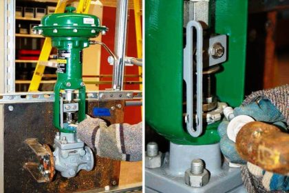
The operation of a control valve involves positioning its movable part (the plug, ball or vane) relative to the stationary seat of the valve. The purpose of the valve actuator is to accurately locate the valve plug in a position dictated by the control signal.

Contents
Pneumatic Control Valve ActuatorsPiston actuatorsDiaphragm actuatorsReverse acting (spring-to-extend)Direct acting actuator (spring-to-retract)Articles You May Like :What is Partial Stroke Test ?Valve Questions & AnswersWhat is Hydraulic Actuator ?Snap Acting Relay PrincipleWhat is Lift Check Valve ?

The actuator accepts a signal from the control system and, in response, moves the valve to a fully-open or fully-closed position, or a more open or a more closed position (depending on whether ‘on/off’ or ‘continuous’ control action is used).

There are several ways of providing this actuation.

  • Pneumatic.
  • Electric.

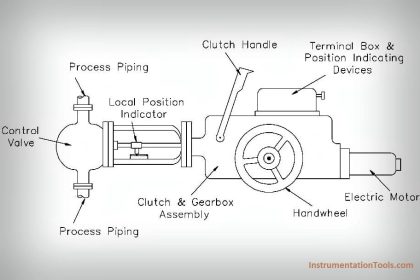
Other significant actuators include the hydraulic and the direct acting types.

Pneumatic Control Valve Actuators

Pneumatic actuators are commonly used to actuate control valves and are available in two main forms;
  • piston actuators
  • diaphragm actuators
Pneumatic Control Valve Actuators

Piston actuators

Piston actuators are generally used where the stroke of a diaphragm actuator would be too short or the thrust is too small. The compressed air is applied to a solid piston contained within a solid cylinder.

Piston actuators can be single acting or double acting, can withstand higher input pressures and can offer smaller cylinder volumes, which can act at high speed.
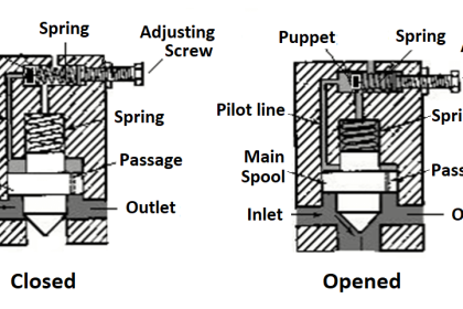
Diaphragm actuators

Diaphragm actuators have compressed air applied to a flexible membrane called the diaphragm. The below Figure shows a rolling diaphragm where the effective diaphragm area is virtually constant throughout the actuator stroke.

These types of actuators are single acting, in that air is only supplied to one side of the diaphragm, and they can be either direct acting (spring-to-retract) or reverse acting (spring-to-extend).

control valve diaphragm actuators

Reverse acting (spring-to-extend)

The operating force is derived from compressed air pressure, which is applied to a flexible diaphragm. The actuator is designed so that the force resulting from the air pressure, multiplied by the area of the diaphragm, overcomes the force exerted (in the opposite direction) by the spring(s).

The diaphragm (Above Figure) is pushed upwards, pulling the spindle up, and if the spindle is connected to a direct acting valve, the plug is opened. The actuator is designed so that with a specific change of air pressure, the spindle will move sufficiently to move the valve through its complete stroke from fully-closed to fully-open.

As the air pressure decreases, the spring(s) moves the spindle in the opposite direction. The range of air pressure is equal to the stated actuator spring rating, for example 0.2 – 1 bar.

With a larger valve and/or a higher differential pressure to work against, more force is needed to obtain full valve movement.

To create more force, a larger diaphragm area or higher spring range is needed. This is why controls manufacturers offer a range of pneumatic actuators to match a range of valves – comprising increasing diaphragm areas, and a choice of spring ranges to create different forces.

The diagrams in Below Figure show the components of a basic pneumatic actuator and the direction of spindle movement with increasing air pressure.

pneumatic actuator

Direct acting actuator (spring-to-retract)

The direct acting actuator is designed with the spring below the diaphragm, having air supplied to the space above the diaphragm. The result, with increasing air pressure, is spindle movement in the opposite direction to the reverse acting actuator.

The effect of this movement on the valve opening depends on the design and type of valve used, and is illustrated in Above Figure.

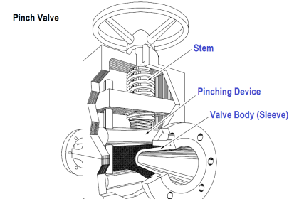
There is however, an alternative, which is shown in Below Figure. A direct acting pneumatic actuator is coupled to a control valve with a reverse acting plug (sometimes called a ‘hanging plug’).

direct acting pneumatic actuator

The choice between direct acting and reverse acting pneumatic controls depends on what position the valve should revert to in the event of failure of the compressed air supply. Should the valve close or be wide-open?

This choice depends upon the nature of the application and safety requirements. It makes sense for steam valves to close on air failure, and cooling valves to open on air failure.

The combination of actuator and valve type must be considered.

The below Figures sow the net effect of the various combinations.

control valve actuator action and valve action

Control Valve Failure Action

Article Source : spirax sarco

Articles You May Like :

What is Partial Stroke Test ?

Valve Questions & Answers

What is Hydraulic Actuator ?

Snap Acting Relay Principle

What is Lift Check Valve ?

Don't Miss Our Updates
Be the first to get exclusive content straight to your email.
We promise not to spam you. You can unsubscribe at any time.
Invalid email address
You've successfully subscribed !

Continue Reading

Solving Control Valve Hunting: Instrument Troubleshooting
Solenoid Valve Troubleshooting Practices
Solenoid Valve Selection Criteria
Difference Between Linear Actuator and Rotary Actuator
Control Valve Tips and Tricks
Control Valve Interview Questions and Answers
Share This Article
Facebook Whatsapp Whatsapp LinkedIn Copy Link
Share
5 Comments
  • Shanmugam says:
    October 23, 2016 at 4:41 am

    fantastic explanation

    Reply
  • vivekananda says:
    October 23, 2016 at 11:23 am

    sir please explain the working of Reverse Air Bag House

    Reply
  • Mauricio Cordeiro says:
    December 3, 2016 at 12:34 am

    Perfect tex!, excellent explanation of the operation control valve and its main accessory. Congratulations

    Reply
  • Anoop says:
    March 16, 2017 at 1:36 pm

    Thanks a lot

    Reply
  • Md Rizwanullah says:
    February 26, 2018 at 4:21 am

    Nice information sir

    Reply

Leave a Reply Cancel reply

Your email address will not be published. Required fields are marked *

Stay Connected

128.3kFollowersLike
69.1kFollowersFollow
208kSubscribersSubscribe
38kFollowersFollow

Categories

Explore More

What is Pump Cavitation? How to Avoid Cavitation?
Basics of Ball Valves
Types of Control Valves Noise
Short Notes on Different Valve Types
Basic Steps and Procedure for the Repair of Control Valve
Basics of Gate Valves
JT Valve Working Principle
Control Valve Recommended Practices for Harsh Process Conditions
Control Valve Passing Problem after Overhauling Job
Automated Block Valve (ABV)

Keep Learning

How to Remove Control Valve Stem Packing Procedure

The Replacement Procedure for Control Valve Stem Packing

Pressure Control Valve

What is Pressure Control Valve?

Snap Acting Relay Working Principle

Snap Acting Relay Working Principle

Pneumatic Valves Questions & Answers

Pneumatic Valves Questions & Answers

four-way-solenoid-valve-diagram

Four Way Solenoid Valve Working Principle

Control Valves Leakage Classifications

Control Valves Leakage Classifications

port-guided globe valve plug

What is Port-guided Globe Valve ?

Stop Check valve

What is Stop Check valve ?

Discover More

Advantages & Disadvantages of Oil Circuit Breakers

Advantages & Disadvantages of Oil Circuit Breakers

Digital to Analog Converters Objective Questions

Digital to Analog Converters Objective Questions

Simatic Hardware Configuration

Configuration of Profibus Network in Siemens PLC

What is Cloud Computing

What is Cloud Computing? Types of Cloud Services, Components

Signal Strength of Guided-wave Radar Level Instrument

Signal Strength of Guided-wave Radar Level Instrument

Control Valves Classification

Classification of Control Valves

Different PLC available in the Simatic S7 generation

Overview of SIEMENS PLC – S7-1500, S7-1200, S7-400, S7-300

Difference Between LDR and Photodiode

Difference Between LDR and Photodiode

Follow US
All rights reserved. Reproduction in whole or in part without written permission is prohibited.
Welcome Back!

Sign in to your account

Username or Email Address
Password

Lost your password?