Inst ToolsInst ToolsInst Tools
  • Ask
  • Courses
  • Videos
  • Q & A
    • Interview
      • Instrumentation
      • Electronics
      • Electrical
      • Practical Questions
    • MCQ
      • Instrumentation MCQ
      • Electrical MCQ
      • Electronics MCQ
      • Control Systems MCQ
      • Analog Electronics MCQ
      • Digital Electronics MCQ
      • Power Electronics MCQ
      • Microprocessor MCQ
      • Multiple Choice Questions
  • EE
    • Electronics
      • Electronics Q & A
      • Electronic Basics
      • Electronic Devices & Circuits
      • Electronics Animation
      • Digital Electronics
    • Electrical
      • Electrical Basics
      • Electrical Q & A
      • Power Electronics
      • Electrical Machines
      • Electrical Animation
      • Power Systems
      • Switchgear & Protection
      • Transmission & Distribution
  • Measure
    • Control Valves
    • Calibration
    • Temperature
    • Pressure
    • Flow
    • Level
    • Analyzers
    • Switches
    • Vibration
    • Solenoid Valve
  • Control
    • PLC Tutorials
    • Control Systems
    • Safety Instrumented System (SIS)
    • Communication
    • Fire & Gas System
  • More
    • Design
    • Tools
    • Animation
    • Basics
    • Formulas
    • Standards
    • TextBooks
    • Common
    • Software
    • Excel Tools
    • Erection & Commissioning
    • Process Fundamentals
    • Videos
    • Books
Search
All rights reserved. Reproduction in whole or in part without written permission is prohibited.
Reading: Impedance in RLC Circuits
Share
Notification Show More
Font ResizerAa
Inst ToolsInst Tools
Font ResizerAa
  • Courses
  • PLC Tutorials
  • Control Systems
Search
  • Ask
  • Courses
  • Videos
  • Q & A
    • Interview
    • MCQ
  • EE
    • Electronics
    • Electrical
  • Measure
    • Control Valves
    • Calibration
    • Temperature
    • Pressure
    • Flow
    • Level
    • Analyzers
    • Switches
    • Vibration
    • Solenoid Valve
  • Control
    • PLC Tutorials
    • Control Systems
    • Safety Instrumented System (SIS)
    • Communication
    • Fire & Gas System
  • More
    • Design
    • Tools
    • Animation
    • Basics
    • Formulas
    • Standards
    • TextBooks
    • Common
    • Software
    • Excel Tools
    • Erection & Commissioning
    • Process Fundamentals
    • Videos
    • Books
Follow US
All rights reserved. Reproduction in whole or in part without written permission is prohibited.
Inst Tools > Blog > Electrical Theory > Impedance in RLC Circuits

Impedance in RLC Circuits

Last updated: July 31, 2018 12:15 am
Editorial Staff
Electrical Theory
No Comments
Share
3 Min Read
SHARE

Impedance in an R-C-L series circuit is equal to the phasor sum of resistance, inductive reactance, and capacitive reactance (Figure 8).

relationship between resistance, reactance, and impedance

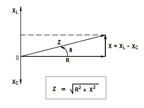
Figure 8 : Series R-C-L Impedance-Phasor

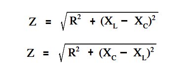
The below Equations are the mathematical representations of impedance in an R-C-L circuit. Because the difference between XL and XC is squared, the order in which the quantities are subtracted does not affect the answer.

impedance in an R-C-L Circuit equation

Example:

Find the impedance of a series R-C-L circuit, when R=6Ω, XL = 20Ω and XC = 10Ω (Figure 9).

Simple R-C-L Circuit

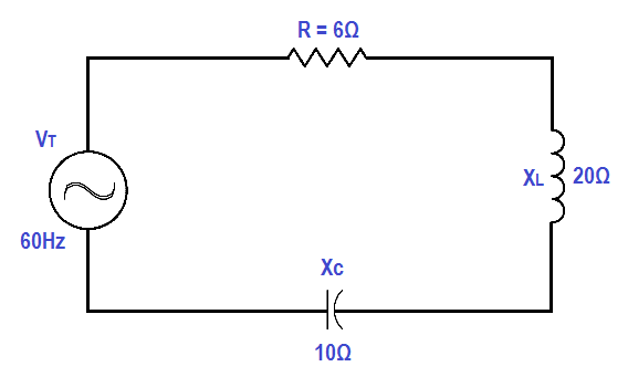
Figure 9 : Simple R-C-L Circuit

Solution:

Z = √ { R2 + (XL – XC)2 }

Z = √ { 62 + (20 – 10)2 }

Z = √136

Z = 11.66 Ω

Impedance in a parallel R-C-L circuit equals the voltage divided by the total current.

The below Equation is the mathematical representation of the impedance in a parallel R-C-L circuit.
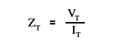
Impedance in a parallel R-C-L circuit

where
ZT = total impedance (Ω)
VT = total voltage (V)
IT = total current (A)

Total current in a parallel R-C-L circuit is equal to the square root of the sum of the squares of the current flows through the resistance, inductive reactance, and capacitive reactance branches of the circuit.

The below Equations are the mathematical representations of total current in a parallel R-C-L circuit. Because the difference between IL and IC is squared, the order in which the quantities are subtracted does not affect the answer.

parallel RCL Circuit Current equation

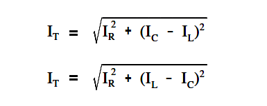
where IC>IL, first equation applies and when where IL >IC, the second equation applies.

where

IT = total current (A)
IR = current through resistance leg of circuit (A)
IC = current through capacitive reactance leg of circuit (A)
IL = current through inductive reactance leg of circuit (A)

Example:

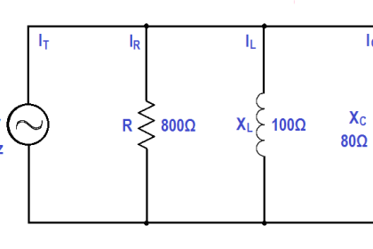
A 200 Ω resistor, a 100 Ω XL , and an 80 Ω XC are placed in parallel across a 120V AC source (Figure 10). Find: (1) the branch currents, (2) the total current, and (3) the impedance.

Parallel RLC Circuit

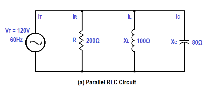
Figure 10 : Simple Parallel R-C-L Circuit

Solution:

1. Branch currents

IR = VT/R = 120/200 = 0.6A

IL = VT/XL = 120/100 = 1.2A

IC = VT/XC = 120/80 = 1.5A

2. Total current

IT = √ { IR2+ (IC – IL)2 }

IT = √ { 0.62+ (1.5 – 1.2)2 }

IT = √ { 0.36 + 0.09 }

IT = √0.45 = 0.671 A

3. Impedance

Z = VT / IT

Z = 120 / 0.671

Z = 178.8 Ω

Don't Miss Our Updates
Be the first to get exclusive content straight to your email.
We promise not to spam you. You can unsubscribe at any time.
Invalid email address
You've successfully subscribed !
Moving Iron Vane Meter Movement
Schematic Diagram
Ground Detector Principle
Calculate Power in Series RL Circuit
Single Line Diagram
Share This Article
Facebook Whatsapp Whatsapp LinkedIn Copy Link
Share
Leave a Comment

Leave a Reply Cancel reply

Your email address will not be published. Required fields are marked *

Stay Connected

128.3kFollowersLike
69.1kFollowersFollow
208kSubscribersSubscribe
38kFollowersFollow

Categories

Recent Comments

  • Guifty Shimica on Top Non-PLC Certification Courses for Automation Professionals
  • Guifty Shimica on Top Non-PLC Certification Courses for Automation Professionals
  • MIHARITSOA Aina Sitraka on Top Non-PLC Certification Courses for Automation Professionals
  • Vaishnavi on Free Instrumentation Course for Trainee Engineers

Related Articles

Resistor Y and Delta Network Calculation

Y and Delta Resistor Network Calculations

relationship between resistance, reactance, and impedance

Impedance

Center Tap Full-Wave Rectifier

Full-Wave Rectifier Circuit

Leading Power Factor

Power Factor

Transformer voltage and turns ratio

Transformer Voltage Ratio

Electric Short Circuit

Electric Circuit : Open & Short Circuits

Series - Wound DC Motor

Series-Wound Motor

Motor Rotating Magnetic Field

AC Motor Theory

More Articles

Instrumentation and Control (I&C) Design

Instrumentation and Control (I&C) Design

Logic for Always ON and Always OFF bit

Always ON and OFF Bit using Ladder Logic and Statement List

Instrumentation Design Details

I&C Engineer Roles & Responsibilities – Instrumentation Design

Effect of Lead Wire Resistance on RTD

Effect of Lead Wire Resistance on RTD

Replace Failed Motors Quickly and Easily

Replace Failed Motors Quickly and Easily

Proportional Control Theory

Proportional-only Offset

Analog Measurement using Ladder Logic

Analog Measurement using Ladder Logic

DC Machine

DC Machines Construction

Follow US
All rights reserved. Reproduction in whole or in part without written permission is prohibited.
Welcome Back!

Sign in to your account

Username or Email Address
Password

Lost your password?