Welcome back with SIEMENS PLCs, today we are going to continue discussing the different PLC troubleshooting techniques, if you are interested in such topics you have to read these topics:
Today we are going to speak about various helpful PLC tools such as the Diagnostic Buffer, how to use it, and how it can help us that is what we are going to speak about.
The function of the Diagnostic Buffer at SIEMENS PLCs?
The operating system of the PLC processor enters the errors detected by the CPU and the diagnostics-capable modules into the diagnostics buffer in the order in which they occurred.
This includes the following events:
- Every mode change of the CPU (POWER UP, change to STOP mode, change to RUN mode)
- Every hardware and diagnostic error interrupts
Advantages of the Diagnostic Buffer
- After the CPU has changed to STOP mode, you can evaluate the last events prior to the STOP so that you can locate and identify the cause of the STOP.
- You can detect and eliminate the causes of errors more quickly and thus increase the availability of the system.
- You can evaluate and optimize the dynamic system response.
Diagnostic Buffer for SIEMENS PLC
Before going through that tool, you have to go online to open and deal with the diagnostic buffer to determine the status of your PLC.
If you do not know how to go online with your PLC please check the previous article (here)
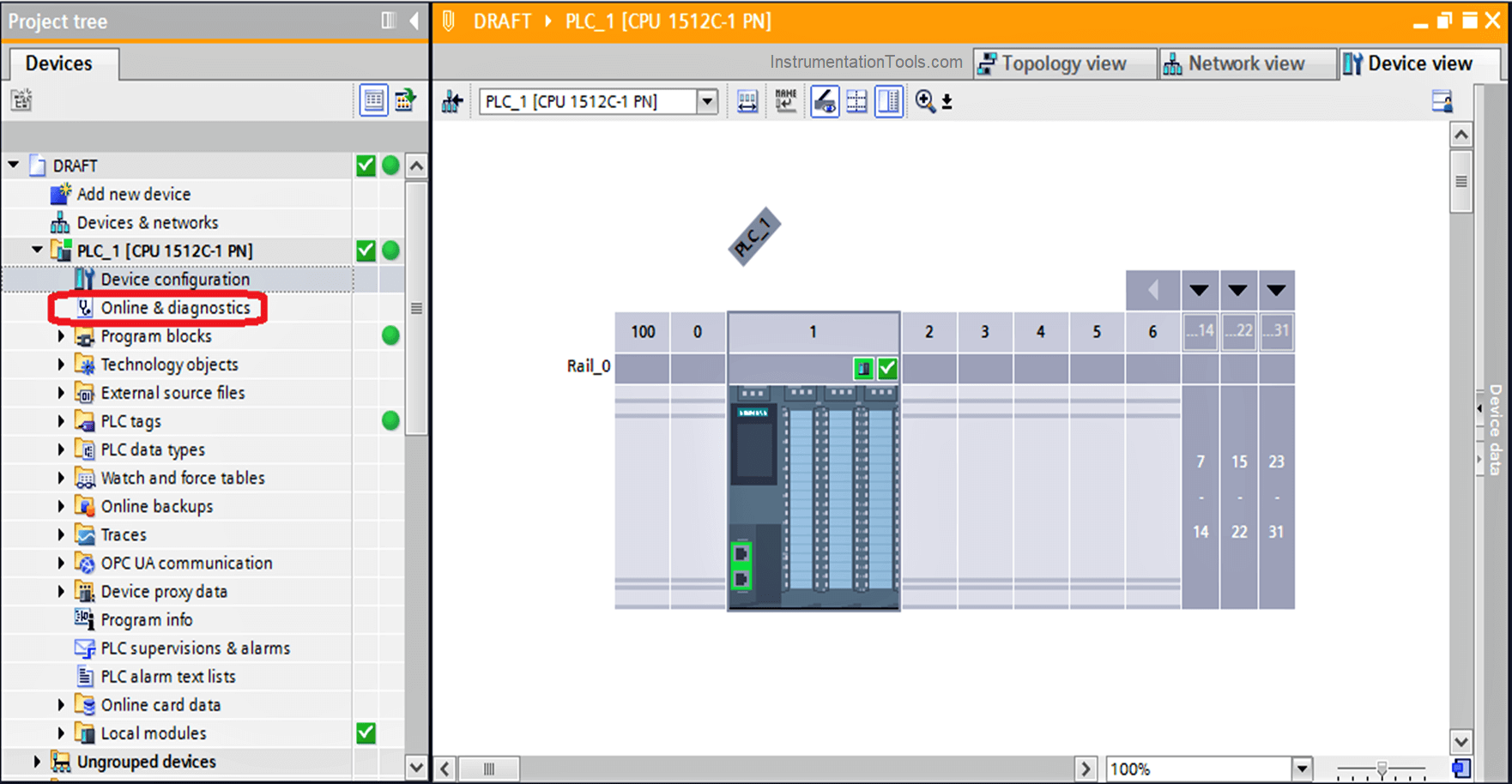
Now and after going Online click on “Online & diagnostics” on the project tree as shown in the next figure.
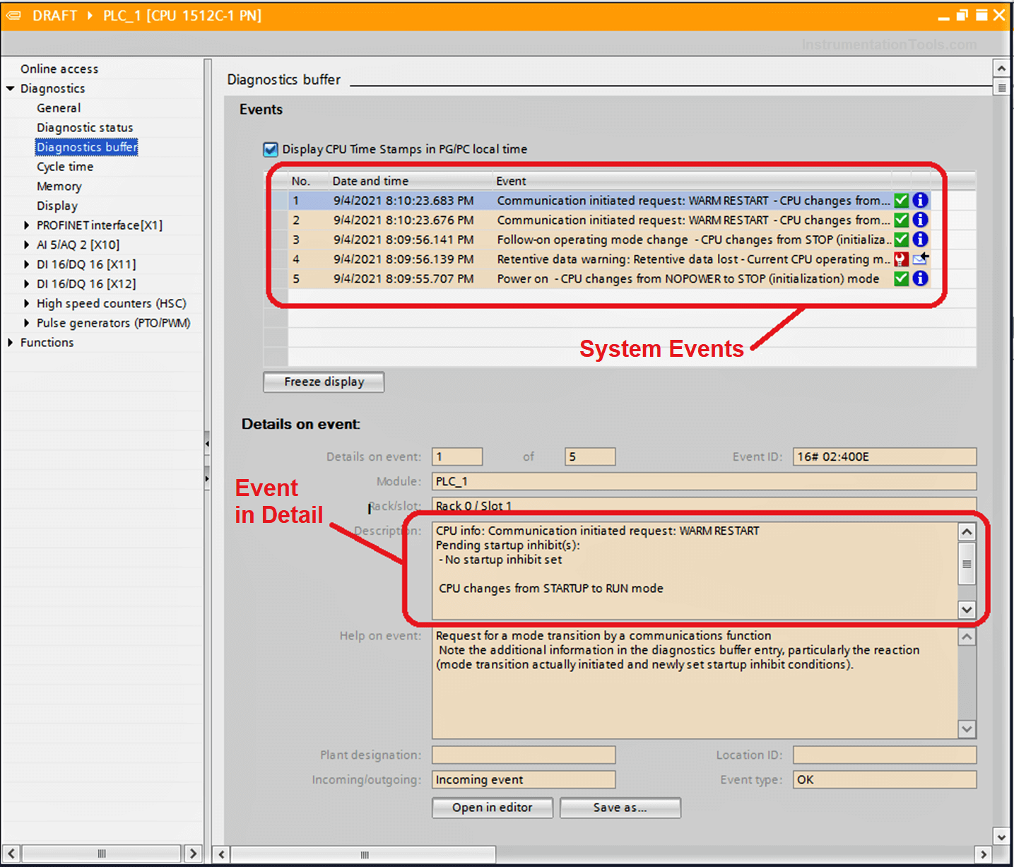
As we can see in the next figure here are some of the system events that are ordered with the date and time that is occurred in.
Note
The diagnostics buffer is a ring buffer. With the S7-1200 CPUs, the maximum number of entries is 50.
When the diagnostics buffer is full and a further entry needs to be made, all existing entries are shifted one position (which means that the oldest entry is deleted) and the new entry is made at the first position that is now free (FIFO principle: first in, first out).
Siemens PLC Example
Here we will see a simple example to know how a diagnostic buffer can help us in troubleshooting.
We have here a situation that after some time of PLC running, the PLC goes to STOP mode by itself and after resetting the PLC it occurs again.
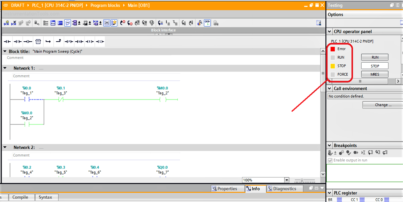
Download: PLC Program
After going to the PLC diagnostic buffer, we will see what is really happing inside
As we can see in the next figure the PLC goes to STOP mode because of the cycle time exceeded the limit of the scan cycle time, and that forced the CPU to go to the STOP mode by itself.
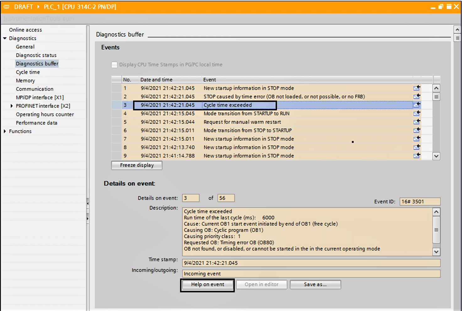
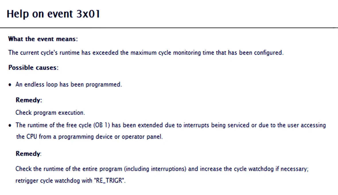
If you still cannot understand what is going on you can click on “Help on the event” in the previous figure to open the Help dictionary.
We will see that there might be an infinity loop in our PLC code, or there is any reason that pushes the cycle time over the limit of the scan cycle time.
So, if we go back again to our code, we will find out that by mistake (obviously not) we have made an infinity loop in our code as we can see in the next figure.
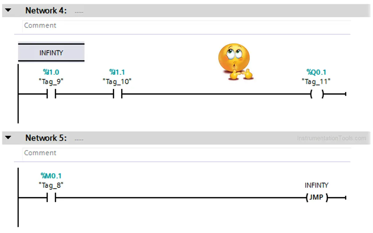
So, after going back to our code and editing that mistake, we will have a healthy PLC performance again.
Thanks for being here and wait for more Automation articles.
If you liked this article, then please subscribe to our YouTube Channel for Instrumentation, Electrical, PLC, and SCADA video tutorials.
You can also follow us on Facebook and Twitter to receive daily updates.
Read Next:
- Yokogawa DCS Tutorials
- PLC System Cabinet Health Checks
- Communication Protocols in PLC
- SFC Language in PLC Programming
- DCS in Industrial Automation
