Inst ToolsInst ToolsInst Tools
  • Courses
  • Videos
  • Q & A
    • Interview
      • Instrumentation
      • Electronics
      • Electrical
      • Practical Questions
    • MCQ
      • Instrumentation MCQ
      • Electrical MCQ
      • Electronics MCQ
      • Control Systems MCQ
      • Analog Electronics MCQ
      • Digital Electronics MCQ
      • Power Electronics MCQ
      • Microprocessor MCQ
      • Multiple Choice Questions
  • EE
    • Electronics
      • Electronics Q & A
      • Electronic Basics
      • Electronic Devices & Circuits
      • Electronics Animation
      • Digital Electronics
    • Electrical
      • Electrical Basics
      • Electrical Q & A
      • Power Electronics
      • Electrical Machines
      • Electrical Animation
      • Power Systems
      • Switchgear & Protection
      • Transmission & Distribution
  • Measure
    • Control Valves
    • Calibration
    • Temperature
    • Pressure
    • Flow
    • Level
    • Analyzers
    • Switches
    • Vibration
    • Solenoid Valve
  • Control
    • PLC Tutorials
    • Control Systems
    • Safety Instrumented System (SIS)
    • Communication
    • Fire & Gas System
  • More
    • Design
    • Tools
    • Animation
    • Basics
    • Formulas
    • Standards
    • TextBooks
    • Common
    • Software
    • Excel Tools
    • Erection & Commissioning
    • Process Fundamentals
    • Videos
    • Books
Search
All rights reserved. Reproduction in whole or in part without written permission is prohibited.
Reading: Guided-wave Radar Asset Management Parameters
Share
Notification Show More
Font ResizerAa
Inst ToolsInst Tools
Font ResizerAa
  • Courses
  • PLC Tutorials
  • Control Systems
Search
  • Courses
  • Videos
  • Q & A
    • Interview
    • MCQ
  • EE
    • Electronics
    • Electrical
  • Measure
    • Control Valves
    • Calibration
    • Temperature
    • Pressure
    • Flow
    • Level
    • Analyzers
    • Switches
    • Vibration
    • Solenoid Valve
  • Control
    • PLC Tutorials
    • Control Systems
    • Safety Instrumented System (SIS)
    • Communication
    • Fire & Gas System
  • More
    • Design
    • Tools
    • Animation
    • Basics
    • Formulas
    • Standards
    • TextBooks
    • Common
    • Software
    • Excel Tools
    • Erection & Commissioning
    • Process Fundamentals
    • Videos
    • Books
Follow US
All rights reserved. Reproduction in whole or in part without written permission is prohibited.
Inst Tools > Blog > Practical Questions > Guided-wave Radar Asset Management Parameters

Guided-wave Radar Asset Management Parameters

Examine the different configuration parameters for a guided-wave radar transmitter asset management software.

Last updated: January 12, 2021 6:47 pm
Editorial Staff
Practical Questions
No Comments
Share
1 Min Read
SHARE

Examine the different configuration parameter fields for a guided-wave radar transmitter shown in this screenshot (taken on a personal computer running Emerson AMS software, interrogating a Rosemount model 3300 level transmitter), and explain the importance of each one:

Guided-wave Radar Asset Management Parameters

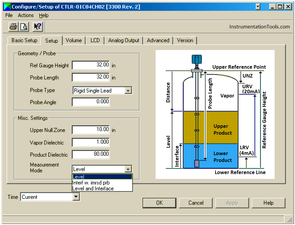
1. Do you think it is realistic to set the span of a GWR transmitter equal to its probe length? Why or why not?

2. What does the selection “Interf w. imrsd prb” mean, especially in comparison with the other measurement mode options?

3. What significance does the “Probe Angle” setting have?

Share your answers and explanation with us through the below comments section.

Read Next:

  • Signal Strength of Guided-wave Radar Level Instrument
  • Guided-Wave Radar Instruments Diagnostics
  • Level Instruments Measuring Velocity
  • Guided Wave Radar Questions and Answers
  • Process Control Automation PLC Quiz

Credits: Tony R. Kuphaldt

Don't Miss Our Updates
Be the first to get exclusive content straight to your email.
We promise not to spam you. You can unsubscribe at any time.
Invalid email address
You've successfully subscribed !

Recommended Articles

Simple Pressure Repeater
Programmable Logic Controller (PLC) Questions and Answers – 1
Determine Effect of Each Fault for Pneumatic Force-balance System
Displacer Level Transmitter 5-point Calibration
Process Control High Level Alarm Fault Analysis
Draw a ladder logic circuit for the electric motor of an air compressor ?
Share This Article
Facebook Whatsapp Whatsapp LinkedIn Copy Link
Share
Leave a Comment

Leave a Reply Cancel reply

Your email address will not be published. Required fields are marked *

Stay Connected

128.3kFollowersLike
69.1kFollowersFollow
208kSubscribersSubscribe
38kFollowersFollow

Categories

Recent Comments

  • William Snyder on Top Non-PLC Certification Courses for Automation Professionals
  • Kamli on Top Free PLC Software
  • Guifty Shimica on Top Non-PLC Certification Courses for Automation Professionals
  • Guifty Shimica on Top Non-PLC Certification Courses for Automation Professionals

Related Articles

Calculate the Magnitude of Hydrostatic Pressure

Calculate the Magnitude of Hydrostatic Pressure

liquid level Measurement

Hydrostatic Level Measurement – Temperature related Density Change Effects

Flapper nozzle system

Flapper Nozzle Questions

liquid flow control system

Practical Process Control System Questions & Answers – 7

Identify Instrumentation Terms in Water Supply System

Identify Instrumentation Terms in Water Supply System

Signal Strength of Guided-wave Radar Level Instrument

Signal Strength of Guided-wave Radar Level Instrument

Determine Calibration Range of Pneumatic Pressure Transmitter

Determine Calibration Range of Pneumatic Pressure Transmitter

How Much Pressure indicated by Micromanometer

How Much Pressure Indicated by Micromanometer?

More Articles

Difference between Router, Switch, and Hub

Difference between Router, Switch, and Hub

Stepper Motor Parts

Stepper Motor MCQ

Digital Electronics Multiple Choice Questions

Counter Implementation Objective Questions

Pipe Elbow Sudden Burst

A Pipe Elbow Sudden Burst Fatalities and Wrecked Panel Instrumentation

Best Online Courses to Learn Electrical Engineering

Best Online Courses to Learn Electrical Engineering

Difference between KW and KVA

Difference between KW and KVA

Exclusive Valve Sequencing

Exclusive Control Valve Sequence

Ladder Diagram Example using Memory Bits and Set Coils

Ladder Diagram Example using Memory Bits and Set Coils

Follow US
All rights reserved. Reproduction in whole or in part without written permission is prohibited.
Welcome Back!

Sign in to your account

Username or Email Address
Password

Lost your password?