In this post, we will understand how to filter digital and analog inputs in a PLC.
As the topic says, filtering is a means to remove unwanted spikes in the signals received in PLC. Its role is to eliminate the fluctuations and pass only proper signal changes at a particular time to the PLC.
Inside a PLC, the filter circuitry comes first and then comes the PLC input processing circuitry, which accepts the final filtered input and uses it for its logic.
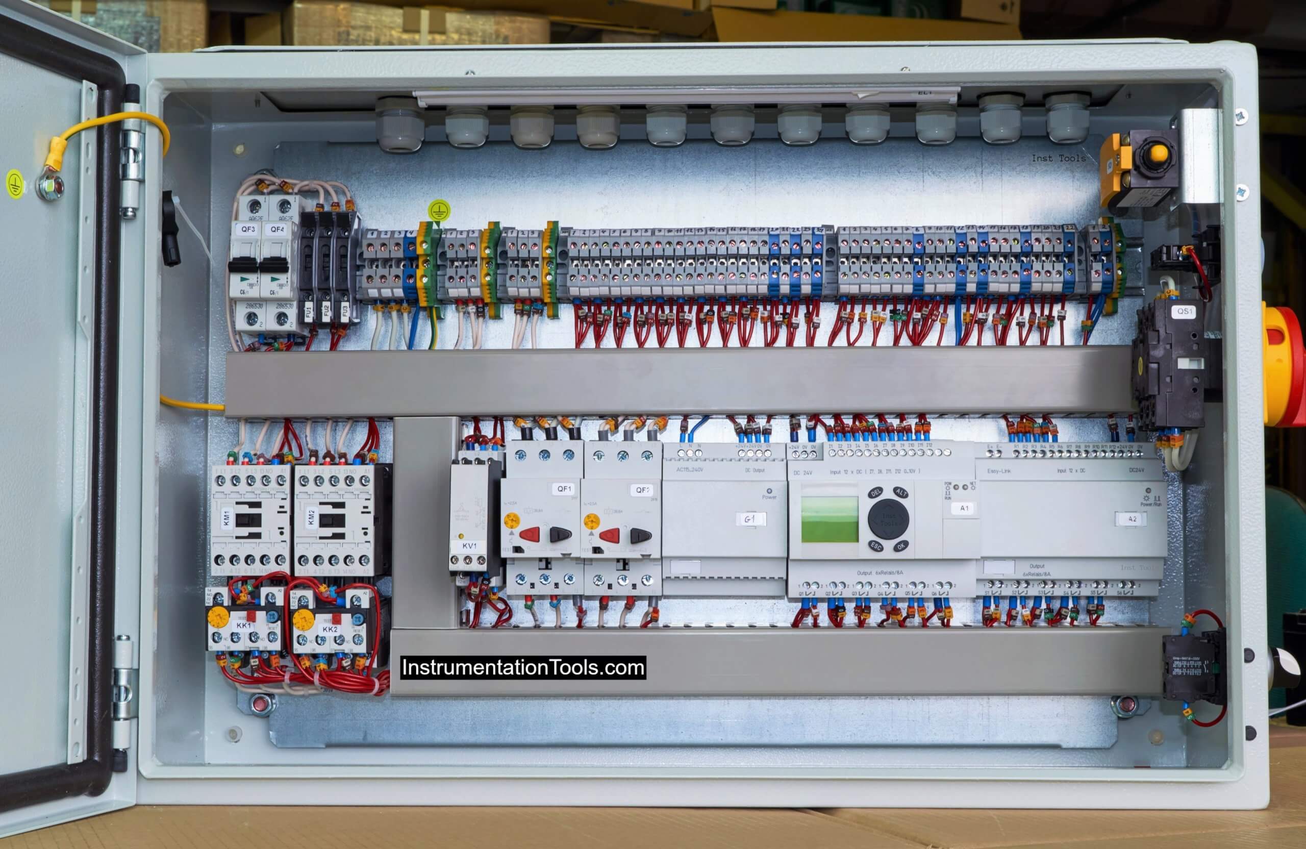
PLC Digital Input Filters
Let us first consider the digital input. The role of input with a filter is to accept a digital field input and pass it to a processing circuit through the filter.
If you see the below image, there are two parts.
First of all, the green circle indicates that the input change will be passed and the red circle shows that the input change will not be passed.
In the first (above) part, there are two changes where there are many fluctuations and that input changes will be bypassed.
There are two changes where there are no fluctuations and that input change will be passed to the processing circuit. The same is the theory with the second (below) part. This is possible by filtering.
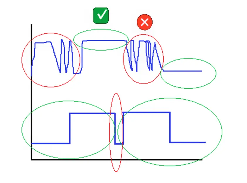
Filtering is defined by a factor or time. Suppose you set a time of 3 ms. The role of the filter is to accept only that input change that stays higher than 3 ms.
If the input changes before 3 ms, then that input will not be considered and will be ignored. This means that short and high-frequency interference pulses will be neglected.
This logic is the same as a debounce timer that we write in the PLC logic.
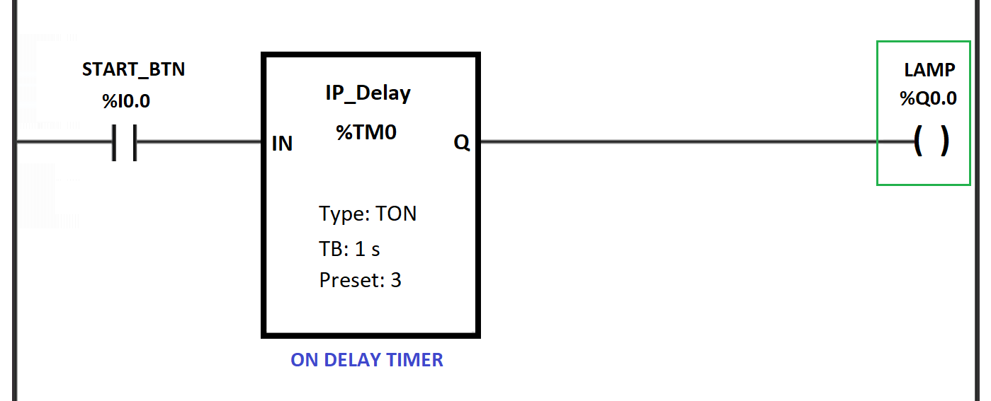
In the below image, the lamp will turn on only when the start button input remains high for 3 seconds.
This is the same logic used in a digital pass filter. It will pass on the input change to the processing part only when that input maintains a state (high or low) for the set time.
Apart from time, as discussed, some PLCs have the option of setting a factor instead of time.
The factor calculates the internal time and decides the level of filtering. Higher the factor value, the higher the filtering power.
PLC Analog Input Filters
Now, let us see the filtering in analog inputs. As analog inputs are variable in nature, the filter logic for them cannot be implemented the same as for digital inputs.
So, in analog inputs, averaging logic is used. The filter will average the values attained in a particular set time and give an average final value for that time.
Refer to the below image for the study.
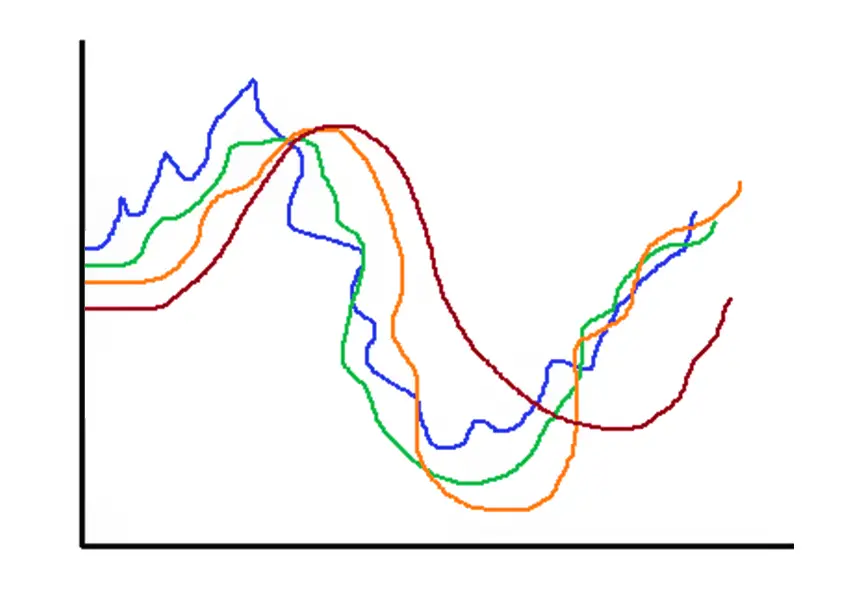
The first one – the blue color has a factor of 1.
The second one – the green color has a factor of 2.
The third one – the orange color has a factor of 3.
The fourth one – the brown color has a factor of 4.
As the value of the filter factor increases, you can see that the shape of the signal improves by filtering the signal at a sharper value.
In a set time, the filter will average the values that it gets from the input; and based on formulas used inside it, it will give the final average output per time.
So, as the filter factor or weightage is increased, we get a finer value of an analog signal with less interference. Normally, a first-pass filter is used for this purpose.
In this way, we conclude that filtering is of great use in reducing unwanted noise from the field input and passing proper values, which will also protect the PLC input circuit from damage; if any high or unwanted spikes occur.
If you liked this article, then please subscribe to our YouTube Channel for Instrumentation, Electrical, PLC, and SCADA video tutorials.
You can also follow us on Facebook and Twitter to receive daily updates.
Read Next:
- What is a Safety Relay?
- List of PLC Spares
- Push button PLC Logic
- Siemens Timer Value
- Allen Bradley Architecture
