Inst ToolsInst ToolsInst Tools
  • Courses
  • Automation
    • PLC
    • Control System
    • Safety System
    • Communication
    • Fire & Gas System
  • Instrumentation
    • Design
    • Pressure
    • Temperature
    • Flow
    • Level
    • Vibration
    • Analyzer
    • Control Valve
    • Switch
    • Calibration
    • Erection & Commissioning
  • Interview
    • Instrumentation
    • Electrical
    • Electronics
    • Practical
  • Q&A
    • Instrumentation
    • Control System
    • Electrical
    • Electronics
    • Analog Electronics
    • Digital Electronics
    • Power Electronics
    • Microprocessor
  • Request
Search
  • Books
  • Software
  • Projects
  • Process
  • Tools
  • Basics
  • Formula
  • Power Plant
  • Root Cause Analysis
  • Electrical Basics
  • Animation
  • Standards
  • 4-20 mA Course
  • Siemens PLC Course
Reading: Emergency Shutdown System Philosophy
Share
Font ResizerAa
Inst ToolsInst Tools
Font ResizerAa
  • Courses
  • Design
  • PLC
  • Interview
  • Control System
Search
  • Courses
  • Automation
    • PLC
    • Control System
    • Safety System
    • Communication
    • Fire & Gas System
  • Instrumentation
    • Design
    • Pressure
    • Temperature
    • Flow
    • Level
    • Vibration
    • Analyzer
    • Control Valve
    • Switch
    • Calibration
    • Erection & Commissioning
  • Interview
    • Instrumentation
    • Electrical
    • Electronics
    • Practical
  • Q&A
    • Instrumentation
    • Control System
    • Electrical
    • Electronics
    • Analog Electronics
    • Digital Electronics
    • Power Electronics
    • Microprocessor
  • Request
Follow US
All rights reserved. Reproduction in whole or in part without written permission is prohibited.
Inst Tools > Blog > Safety Instrumented System (SIS) > Emergency Shutdown System Philosophy

Emergency Shutdown System Philosophy

Last updated: March 28, 2019 2:42 pm
Editorial Staff
Safety Instrumented System (SIS)
2 Comments
Share
5 Min Read
SHARE

The Emergency Shutdown System (ESD) is designed to protect the personnel, plant, equipment and the environment against pollution. The purpose of the ESD system is to monitor process safety parameters and activate or shutdown the process system and/or the utilities if these parameters deviate from normal conditions.

Contents
Emergency Shutdown System PhilosophyResetting philosophy Field Equipment Reset Start-up and Maintenance inhibit/ Override

Emergency Shutdown System Philosophy

Emergency Shutdown System Philosophy

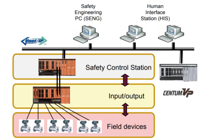
Fig : Safety Layer Protection.

Usually there are several levels of shutdown:

  • ESD 0 :                       Total emergency shutdown  with abandon of platform
  • ESD 0.1 :                    Black shutdown
  • ESD 1 :                       Total plant emergency shutdown
  • ESD 2 :                       Total process shutdown
  • ESD 3 :                       Local unit shutdown

The ESD system operates in a fail safe mode, i.e. de-energized status of any digital sensor (input) or actuator (output), and fault detection of any critical system component and field inputs/outputs shall result in an action that will bring the plant to the safe condition (energised in normal condition).

Setting sequence of the ESD is as follows :

  • ESD alarm level is sent to the operating console to advice the operator on the process and ESD displays
  • ESD alarm may be acknowledged from Operating Console

Packages start-up sequence is initiated after ESD logic reset as per the following sequence :

  • ESD logic is reset at Operating Console
  • Operator to restart packages locally and manually

Motors start-up sequence is initiated after ESD logic reset as per the following sequence :

  • ESD logic is reset at Operating Console
  • Operator to restart manually motors at Operating console or locally

The control valve can be controlled by the PCS when the ESD logic is reset.

Resetting philosophy

Further to a shutdown, the related ESD levels need to be individually and manually reset by the Operation Console operator. The ESD level can be reset only if the upper ESD level is in normal condition.

Resetting sequence is as follows :

  • The operator is informed on the ESD and process displays that the ESD level can be reset
  • ESD level alarm return to normal conditions only when all ESD causes have disappeared or have been inhibited and the ESD level reset is carried out on the ESD display of theOperation Console

 Field Equipment Reset 

Unless otherwise specified, SDVs/BDVs valves (shutdown or Blowdown) are locally manually reset.

Resetting sequence is as follows :

  • ESD logic is reset at Operation Console
  • Valve is manually reset (permissive reset)
  • Valve is actuated at Operation Console

Local permissive resets are input to the ESD system.

Start-up and Maintenance inhibit/ Override

In order to be able to start-up equipment or sections process, it is necessary to inhibit some inputs to the ESD system, as sensor signal may be in abnormal state prior to start-up and could cause a shutdown. Such inhibits are designated as “start-up inhibits”.

While Maintenance inhibits are set from the  maintenance / inhibit console for maintenance purpose

Each inhibit function is reset automatically either by the sensor signal reverting to normal state or after a predetermined time delay. The automatic resets are achieved by the Safety Shutdown System.

Start up / maintenance inhibits are set manually by the operator from the Operation Console through a touch-target on process control displays which appear only when the signal to be inhibited is in alarm and not in technical fault.

Start –up / Maintenance inhibit statuses are indicated on the process control displays and ESD displays of the Operation Console and printed on the events printer.

This type of logic usually have 1 signals output and 3 input status that are shown in the control room,

 Input : 

  1. keyswitch Maintenance Override “Enable”
  2. Maintenance Override Command “Changed”

Output :

  1. Maintenance Override Status “Accepted”

The logic are :

  1. Maintenance Override Status “Accepted” activated if Keyswitch maintenance override and Override Command is activated
  2. Maintenance Override Status “Accepted”is deactivated. If Keyswitch maintenance override is deactivated and Master Reset is activated

Author : Iqbal Matondang

Articles You May Like :

Rupture disks

ESDV : How it Works ?

Probability of Failure on Demand

Safety Instrumented System Example

Burner Management System (BMS)

Don't Miss Our Updates
Be the first to get exclusive content straight to your email.
We promise not to spam you. You can unsubscribe at any time.
Invalid email address
You've successfully subscribed !

Continue Reading

SIS Maintenance – Safety Instrumented System
What is Maintenance Override Switch (MOS) ?
Importance of Safety Integrity Level
Safety Instrumented System Module Failure
Safety Instrumented Systems Online Exam
SIS Instrument Sharing – Transmitters Shared for BPCS and SIS Example
Share This Article
Facebook Whatsapp Whatsapp LinkedIn Copy Link
Share
2 Comments
  • Qadir Mohtasham says:
    April 2, 2019 at 1:58 am

    Great and useful

    Reply
  • Kiran Dewoo says:
    June 20, 2019 at 12:35 am

    Hye, thanks for these very useful and helpful articles. I am learning a lot due to your posts. My respect to you Sir.

    Well i need a little more of your knowledge and help. Please , is it possible to have these precious text in a printable format??

    Thanks a lot

    Kiran Dewoo

    Reply

Leave a Reply Cancel reply

Your email address will not be published. Required fields are marked *

Stay Connected

128.3kFollowersLike
69.1kFollowersFollow
210kSubscribersSubscribe
38kFollowersFollow

Categories

Explore More

SIS – Safety Instrumented System Example
De-energize to Safe Loop philosophy
Bathtub Curve
Safety Instrumented System (SIS) Worksheets and Documents
SIS Final Control Elements
Safety Integrity Level (SIL)
Rupture disks
Safety Requirement Specifications (SRS) – Safety Instrumented System

Keep Learning

Component De-rating

Component De-rating in Control Systems

Process Override Switch

What is Process Override Switch (POS)?

hipps

What is High Integrity Pressure Protection System?

Transistor Failure Rate Calculation

Transistor Failure Rate Calculation

Proof Testing of Safety Instrumented Systems

Proof Testing of Safety Instrumented Systems

Emergency Shutdown System

What is Emergency Shutdown System (ESD) ?

Functional Safety Engineering

SIS Safety Requirements

P&ID

Over Pressure Protection Devices

Learn More

Structured Text in PLC: Parking Information Systems

Structured Text in PLC: Parking Information Systems

Omron PLC Online Training Course

Omron PLC Online Training Course

PLC Program to Control Motor Speed using VFD Drive

Motor Speed Control using VFD and PLC Programming

Digital Instrument Example

Digital Measuring Instruments – Types, Functions, Advantages, Disadvantages

Percentage-to-Process-Variable-Conversion

Formula for Percentage to Process Variable Conversion

Supervisory Control

Supervisory Control

Diode Rectifier

Bridge Rectifier Working Animation

Relay Motor Logic Circuit

Motor Control Circuits

Menu

  • About
  • Privacy Policy
  • Copyright

Quick Links

  • Learn PLC
  • Helping Hand
  • Part Time Job

YouTube Subscribe

Follow US
All rights reserved. Reproduction in whole or in part without written permission is prohibited.
Welcome Back!

Sign in to your account

Username or Email Address
Password

Lost your password?